Introduction: Tolerance Is Where Precision Becomes Cost
In CNC machining, tolerance is not just a number on a drawing—it directly affects:
•Machining time
•Tooling strategy
•Inspection requirements
•Final cost
Tighter tolerance means more control, more time, and more engineering involvement.
So the real question isn’t just:
“What tolerance can you achieve?”
It’s:
“What tolerance do you actually need?”
This guide gives you a clear, engineering-based answer—so you can balance precision, cost, and manufacturability.
Table of Contents
Our Standard CNC Machining Tolerances
For most CNC machined parts, we operate within the following baseline:
General Tolerance (Default)
•±0.01 mm (±0.0004″)
This applies to:
•Aluminum parts
•Steel components
•Most plastic materials
It covers the majority of:
•Mechanical components
•Enclosures
•Structural parts
Tight Tolerance Capability
For critical features, we can achieve:
•±0.005 mm (±0.0002″)
•In controlled cases: ±0.002 mm (±0.00008″)
These tolerances are typically applied to:
•Bearing fits
•Precision mating parts
•Sealing surfaces
Ultra-Precision (Selective Application Only)
In highly controlled scenarios:
•Temperature-controlled environment
•Specialized tooling
•Advanced inspection
We can push tolerances even further—but only when justified.
Important:
Chasing extreme precision without functional need is one of the fastest ways to increase cost without adding value.
Why Not Everything Should Be Tight Tolerance
Many drawings come in with unnecessarily tight tolerances applied to every dimension.
This creates:
•Longer machining cycles
•Increased inspection time
•Higher rejection risk
•Significant cost increase
Engineering rule:
Tight tolerance should only be applied where function requires it.
Everything else should remain standard.
Key Factors That Affect CNC Machining Tolerance
Tolerance is not just about machines—it’s a system.
1. Material Type
Different materials behave differently during machining:
•Aluminum → stable, easy to control
•Stainless steel → harder, more tool wear
•Plastics → thermal expansion, deformation risk
Insight:
Plastic parts generally require wider tolerances than metals.
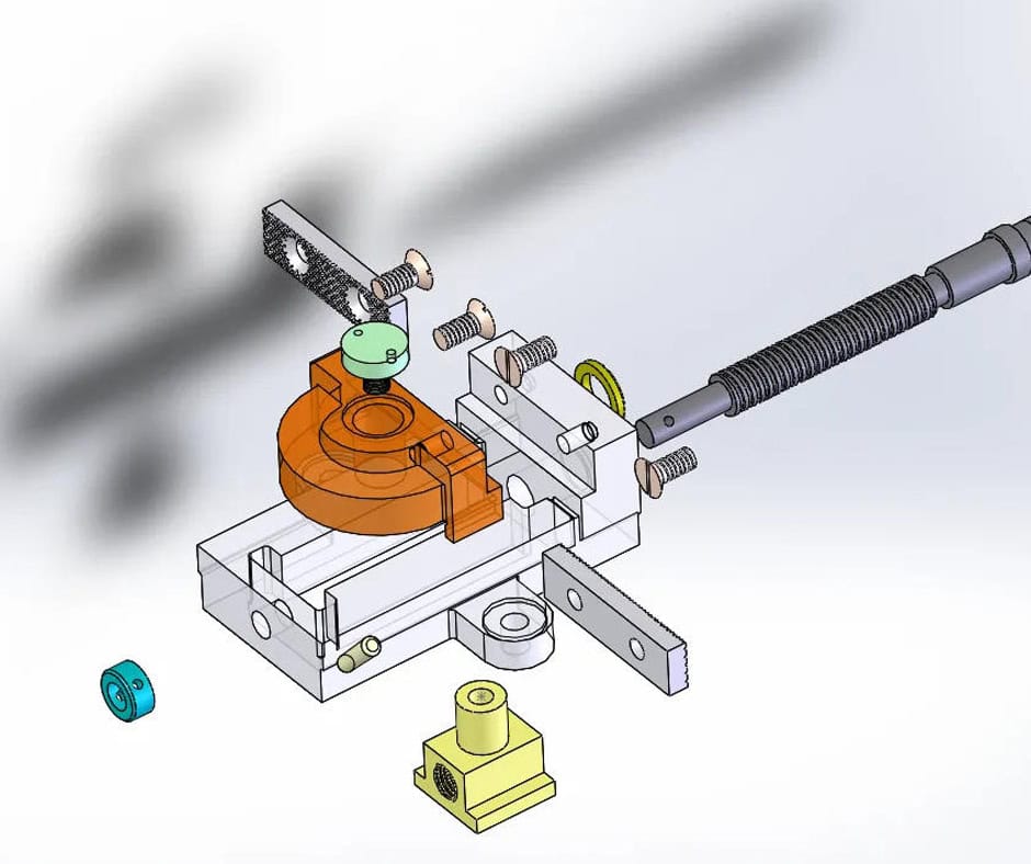
2. Part Geometry
Complexity increases difficulty:
•Thin walls → vibration, deformation
•Deep cavities → tool deflection
•Long features → alignment challenges
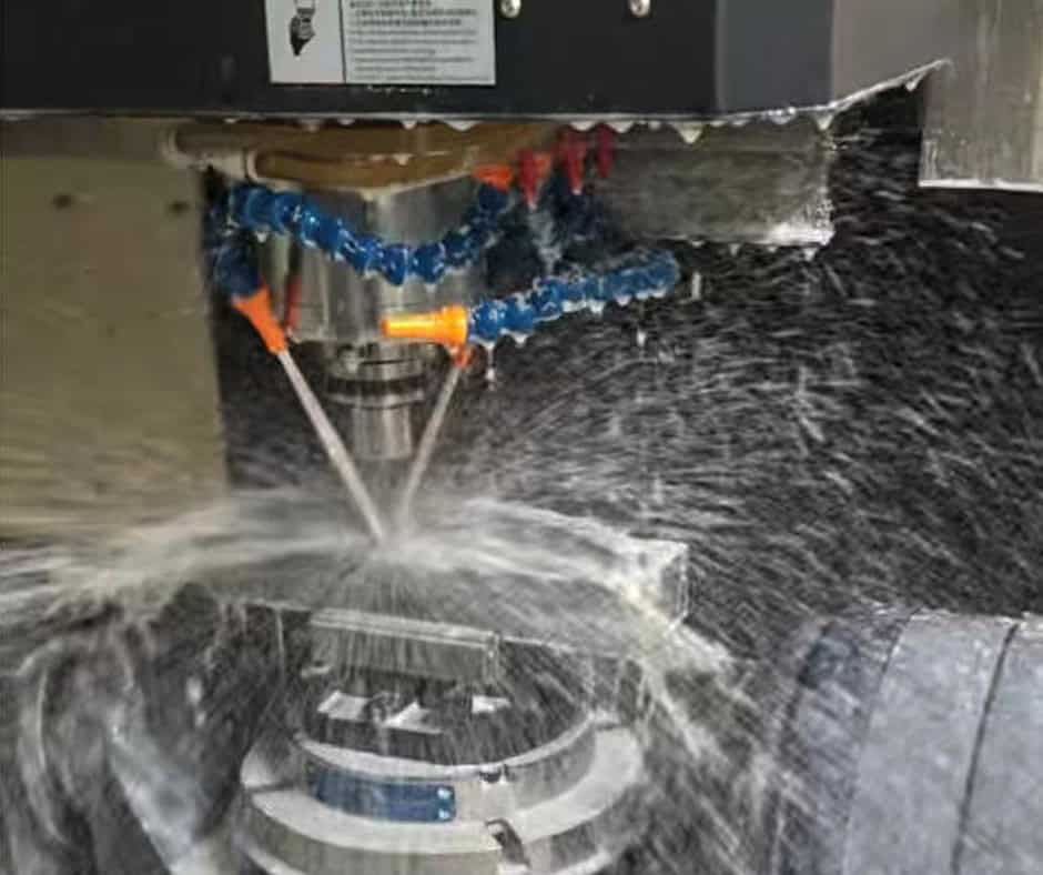
3. Machine Capability
We use:
•3-axis, 4-axis, and 5-axis CNC machines
•High-speed machining centers
•Precision tool calibration
But even the best machines have limits—especially on complex geometries.
4. Tooling and Setup
Tolerance depends heavily on:
•Tool selection
•Tool wear control
•Setup accuracy
•Fixturing stability
5. Environment
Temperature changes—even by a few degrees—can affect:
•Material expansion
•Measurement accuracy
This is critical for ultra-tight tolerances.
Typical Tolerance by Feature Type
Different features require different expectations:
| Feature Type | Typical Tolerance Range |
| Linear dimensions | ±0.01 mm |
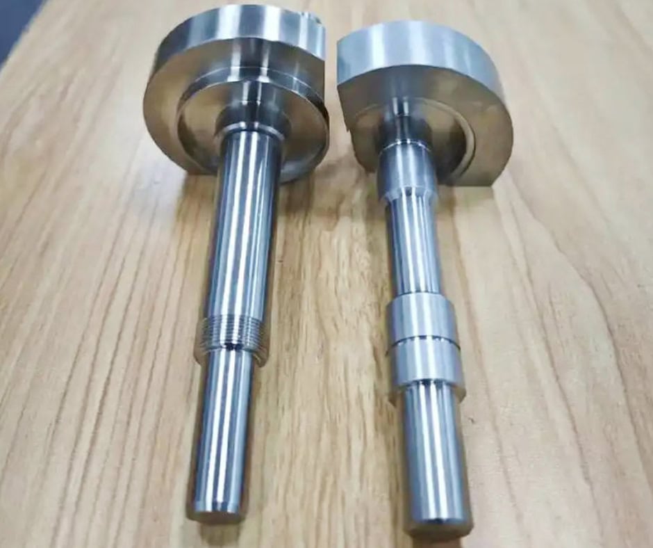
| Hole diameter | ±0.005 mm |
| Shaft diameter | ±0.005 mm |
| Flatness | ±0.01–0.02 mm |
| Surface finish | Ra 0.8–3.2 μm |
Fits and Functional Tolerances
Tolerance only matters in context.
For example:
Clearance Fit
•Easy assembly
•Lower precision required
Interference Fit
•Press fit
•Requires tight tolerance control
Transition Fit
•Balance between both
If your part interacts with another component, tolerance must be defined based on fit function—not arbitrary numbers.
Surface Finish vs Tolerance
•Tolerance → dimensional accuracy
•Surface finish → texture/roughness
You can have:
•Tight tolerance with rough surface
•Smooth surface with loose tolerance
For critical parts (like sealing surfaces), both must be controlled.
Cost vs Tolerance: The Real Trade-Off
Here’s the reality most suppliers won’t say clearly:
Cost increases exponentially as tolerance tightens.
Example trend:
•±0.01 mm → standard cost
•±0.005 mm → +30–50% cost
•±0.002 mm → significantly higher
Why?
•Slower machining
•More inspections
•Higher scrap risk
Design for Manufacturability (DFM): How to Optimize Tolerance
If you want precision without overpaying, follow these rules:
1. Apply Tight Tolerance Only Where Needed
Focus on:
•Mating surfaces
•Functional interfaces
2. Use Standard Tolerances Elsewhere
Let non-critical features remain flexible.
3. Avoid Overly Complex Geometry
Simpler parts = more stable machining
4. Specify Fits, Not Just Numbers
Define:
•H7/g6 fits
•Clearance requirements
Inspection and Quality Control
We use:
•Calipers and micrometers
•Height gauges
•Coordinate Measuring Machines (CMM)
Inspection ensures:
•Dimensional accuracy
•Repeatability
•Compliance with drawings
What If Your Tolerance Is Too Tight?
Instead, we:
•Review your drawing
•Identify over-specified tolerances
•Suggest optimized values
This often results in:
•Lower cost
•Faster lead time
•Same functional performance
Real-World Example
•±0.002 mm across entire part
After review:
•Only 2 critical features needed that level
•Rest adjusted to ±0.01 mm
Result:
•35% cost reduction
•Faster delivery
•No impact on performance
Our Full Capability Beyond Tolerance
We provide:
•CNC machining (3/4/5 axis)
•Sheet metal fabrication
•Surface finishing
•Assembly
With engineering support, not just production.
Final Thoughts: Precision Should Be Intentional
The best designs are not the most precise.
They are the most efficiently precise.
Ready to Get Started?
•Drawings
•Tolerance requirements
•Application details
You’ll get:
•Fast quotation
•Engineering feedback
•Cost optimization suggestions
No over-engineering. No guesswork. Just parts that work.