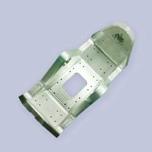
Aerospace parts are rarely difficult because of their overall shape alone. The real challenge is usually hidden in the details: a thin wall that must remain stable after machining, a mounting pattern that has to align with another assembly, a deep pocket that leaves very little room for tool access, or a material that generates excessive heat during cutting.
That is why aerospace CNC machining requires more than a capable CNC machine. The machining strategy has to consider how the part functions, where the critical dimensions are located, how material will be removed, how the component will be held during machining, and how the finished features will be inspected.
SzCrealink provides custom CNC machining for aerospace prototypes, structural components, brackets, housings, mounting parts, adapters, fixtures, and other precision mechanical components. Parts are manufactured from customer drawings and 3D CAD models, with production planned around the actual requirements of the component rather than applying the same machining approach to every part.
What Makes Aerospace CNC Machining Different?
Aerospace components often combine requirements that are individually manageable but difficult when they occur together.
A part may need to be lightweight but rigid, strong but easy to machine, geometrically complex but dimensionally stable, or produced in a small quantity while still requiring controlled inspection.
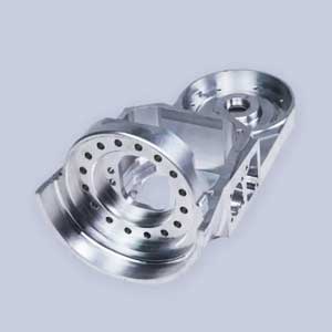
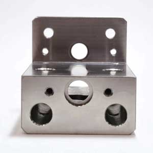
Consider a machined aluminum aerospace bracket.
The bracket may contain several mounting holes, recessed pockets, ribs, threaded holes, and thin outer walls. None of these features is necessarily unusual by itself. The difficulty comes from their relationship.
If the mounting holes are used to position another assembly, their location relative to the primary datum may be critical. If the pockets are intended to reduce weight, removing too much material can reduce stiffness. If the walls are thin, machining forces can move them away from the cutter and cause dimensional errors.
The manufacturing process therefore needs to be designed around the function of the part.
This is one of the main differences between aerospace machining and simply producing a visually complex CNC part.
Start With the Function of the Component
Before selecting tools or programming a CNC machine, it is important to understand what the component actually does.
Different aerospace parts create different manufacturing priorities.
Structural and Lightweight Components
Structural components are often designed with pockets, ribs, bosses, and variable wall thicknesses to reduce weight while maintaining stiffness.
The objective is not simply to remove material.
For example, a deep pocket may reduce weight effectively, but if the remaining wall becomes too thin, the part can become difficult to machine and may not have the stiffness required by the assembly.
The machining plan needs to consider:
Where the load is transferred
Which surfaces provide structural support
Which holes are used for assembly
Where material can safely be removed
How thin the remaining walls can become
How the component will be supported during machining
For large aluminum parts machined from billet, this becomes particularly important because a substantial amount of material may be removed before the final geometry is reached.
Mounting and Interface Parts
Aerospace mounting plates, brackets, adapters, and equipment interfaces often contain many holes and locating surfaces.
In these components, positional accuracy can be more important than achieving an extremely tight tolerance on every individual dimension.
For example, a mounting hole may be specified at a relatively conventional diameter tolerance, while its position relative to a datum is much more important because it determines whether the mating component can be installed correctly.
This is why drawing datums, hole locations, flatness, perpendicularity, and feature relationships need to be considered together.
Housings and Enclosures
Machined aerospace housings frequently combine external mounting features with internal cavities.
A single housing may require:
Internal pockets
Threaded holes
Connector openings
Bearing or component seats
Sealing surfaces
Mounting holes
Flat reference surfaces
Whenever possible, the machining sequence should preserve the relationship between these features. Additional setups can introduce opportunities for accumulated positioning errors, particularly when several features depend on the same reference surface.
Material selection directly affects both the performance of the finished component and the difficulty of manufacturing it.
There is no universal “best” aerospace CNC material. The correct material depends on strength, weight, corrosion resistance, operating temperature, wear, electrical requirements, and the intended function of the component.
Aluminum 6061-T6
6061-T6 is widely used for machined components because it provides a practical combination of strength, corrosion resistance, machinability, and cost.
It is suitable for many:
Mounting brackets
Housings
Panels
Fixtures
Structural supports
Equipment interfaces
Its relatively good machinability also makes it useful for prototypes and low-volume aerospace components where development speed matters.
Aluminum 7075-T6
7075-T6 is often selected when a higher strength-to-weight ratio is required.
Compared with 6061-T6, it generally provides higher strength but can involve different considerations regarding corrosion protection, finishing, and application requirements.
For lightweight structural parts, 7075-T6 can be attractive when reducing mass without sacrificing mechanical performance is an important design objective.
Titanium
Titanium alloys are attractive when strength-to-weight ratio, corrosion resistance, and temperature performance justify their higher material and machining costs.
The machining behavior is very different from aluminum.
Titanium has relatively low thermal conductivity, so cutting heat is not removed from the cutting zone as efficiently. Heat concentration can accelerate tool wear. At the same time, excessive cutting forces can become problematic when machining thin sections.
This means titanium machining requires careful control of cutting parameters, tooling, rigidity, coolant strategy, and tool condition.
For a simple titanium component, the material itself may be the largest cost driver. For a complex thin-wall titanium component, machining time and tool consumption can become equally significant.
Stainless Steel
Stainless steel may be selected when corrosion resistance, strength, wear resistance, or dimensional stability is important.
Compared with aluminum, stainless steel generally requires higher cutting forces and more attention to tool selection and heat management.
It is commonly considered for shafts, adapters, fittings, brackets, mechanical interfaces, and other components where weight is less critical than durability or material performance.
Engineering Plastics
Some aerospace components can benefit from engineering plastics rather than metals.
PEEK, PEI, and other high-performance polymers can be machined into electrical supports, insulating components, spacers, covers, guides, and lightweight mechanical parts.
These materials behave differently from metals during machining. Their lower thermal conductivity and different response to cutting forces require appropriate tooling and cutting conditions.
CNC Milling for Aerospace Components
CNC milling is one of the most widely used processes for aerospace components because it can produce complex prismatic and three-dimensional geometries from solid material.
The important question is not simply whether a part can be milled. It is whether the geometry can be milled efficiently while maintaining the required accuracy.
3-Axis CNC Milling
Three-axis machining can be sufficient for parts with accessible top surfaces, pockets, holes, steps, and relatively straightforward geometry.
It can also be more economical than multi-axis machining when the component does not require complex tool orientations.
As geometry becomes more complicated, additional axes can reduce the number of setups required.
A five-axis machine can orient the cutting tool toward different surfaces while maintaining control over the component in a single machining environment.
This can be particularly useful for:
Angled surfaces
Complex aerospace brackets
Deep cavities
Curved structural components
Components with multiple machined faces
Features requiring controlled tool orientation
However, five-axis machining should not be selected simply because it sounds more advanced.
If a component can be manufactured accurately and economically using three-axis machining with two well-controlled setups, using five-axis machining may not provide a meaningful benefit.
The correct machine configuration depends on the geometry and manufacturing objectives.
CNC Turning and Mill-Turn Machining
Rotational aerospace components are often produced using CNC turning.
Typical examples include:
Shafts
Pins
Bushings
Sleeves
Adapters
Precision spacers
Threaded components
Turning is particularly effective for maintaining concentric cylindrical features when the workpiece can be securely located around its rotational axis.
For components that combine turned and milled geometry, mill-turn machining can reduce the number of separate operations.
This can be valuable when several features must maintain a controlled relationship to the central axis.
Thin-Wall Aerospace Parts Require a Different Approach
Thin-wall machining is one of the areas where manufacturing experience becomes particularly important.
When a cutter removes material from a thin section, the remaining wall can move under cutting forces. The problem is not necessarily that the CNC machine lacks positioning accuracy. The part itself may be physically deflecting during machining.
This creates a common situation:
The machine positions the cutter correctly, but the cutter pushes the workpiece away from its intended position.
Once the cutting force disappears, the material springs back.
The result can be a wall that measures differently from the programmed geometry.
Several factors can help control this problem:
Rigid and appropriate workholding
Optimized cutting parameters
Suitable tool geometry
Controlled material removal
Multiple roughing and finishing stages
Machining sequence designed around residual stress
Inspection after critical finishing operations
For lightweight aerospace structures, these considerations can be more important than simply specifying a tighter machine tolerance.
Workholding and Setup Strategy
Workholding is often underestimated when discussing CNC machining accuracy.
A part cannot be machined accurately if it cannot be held consistently.
For aerospace components with complex geometry, the manufacturer may need to create dedicated fixtures or use carefully positioned soft jaws, locating features, or temporary support structures.
The fixture must hold the part firmly without introducing excessive deformation.
This is especially important for thin-wall components.
A wall that is forced into position by clamping may appear correct during machining. After the fixture is released, it can return toward its natural position and reveal dimensional variation.
The setup strategy therefore needs to consider both the machined condition and the unclamped condition of the final component.
CNC Machining Process: From Drawing to Finished Part
A typical aerospace CNC machining project follows a controlled sequence.
1. Engineering Review
The customer provides the drawing, 3D model, material, quantity, tolerance requirements, surface finish, and other specifications.
The manufacturer reviews the geometry for:
Difficult-to-machine features
Tight tolerances
Deep pockets
Thin walls
Undercuts
Tool access
Workholding requirements
Inspection requirements
This stage is an opportunity to identify manufacturing risks before production starts.
2. Material Preparation
Material is selected according to the drawing and specification.
For critical projects, material certification may also be required to verify the material grade and condition.
3. CAM Programming
The CAM programmer develops toolpaths based on the geometry and machining strategy.
For complex parts, the sequence of operations matters.
A typical strategy may involve roughing first, leaving controlled stock for semi-finishing and finishing. Critical features may be machined later in the process after the component has become more stable.
4. Rough Machining
Roughing removes the majority of unwanted material.
For a large aerospace component machined from billet, this can represent a significant percentage of the total machining time.
The objective is not maximum material removal at any cost. Excessive cutting forces can increase tool wear and cause unnecessary deformation.
5. Semi-Finishing
Semi-finishing establishes a more controlled intermediate geometry.
This stage can provide a stable amount of remaining material for the final finishing operations.
6. Finishing
Finishing operations establish the final dimensions and surface quality.
Different tools and cutting conditions may be used for critical bores, flat surfaces, thin walls, curved surfaces, and threaded features.
7. Inspection
Inspection verifies that the finished component conforms to the drawing.
Depending on the part, inspection can include:
Dimensional measurement
CMM inspection
Bore measurement
Thread inspection
Flatness measurement
Perpendicularity measurement
Surface roughness measurement
Visual inspection
For components with multiple critical datums, inspection should reproduce the functional reference system defined by the drawing rather than measuring dimensions in isolation.
Surface Finishing for Aerospace Parts
CNC machining produces the geometry, but the final surface treatment may be equally important for the intended application.
Aluminum components may require anodizing for improved surface protection and other functional requirements.
Stainless steel parts may require passivation.
Other components may require plating, polishing, painting, or specialized coating processes.
Surface treatment must be considered before machining is completed because coating thickness can affect dimensions.
For example, if a precision bore will receive a coating, the machining allowance and final dimensional requirement need to account for the treatment process.
This is a small detail, but it can determine whether a finished component actually fits its mating part.
Prototype and Low-Volume Aerospace Machining
Prototype and Low-Volume Aerospace Machining
Aerospace development frequently involves prototypes or relatively small production quantities.
The first component may be manufactured to validate:
Form
Fit
Function
Assembly
Weight
Interface dimensions
Manufacturing assumptions
The machining strategy for a prototype should therefore allow engineering feedback.
A supplier that treats a one-piece prototype exactly like a high-volume production order may create unnecessary tooling or setup costs.
For repeat production, however, the priorities change.
Process repeatability, fixture efficiency, tool life, inspection frequency, and production scheduling become increasingly important.
The best manufacturing strategy for one prototype is not necessarily the best strategy for 500 production parts.
How Aerospace CNC Machining Cost Is Determined
The quoted price of an aerospace component is influenced by several variables.
Material is one factor, but machining complexity can have an even larger impact.
A part with a high material-removal ratio can require significantly more machining time than its finished weight suggests.
Other cost drivers include:
Number of setups
Programming time
Tool consumption
Machine time
Material utilization
Tight tolerances
Surface finish
Inspection requirements
Special workholding
Surface treatment
Production quantity
Tight tolerances should therefore be specified where they provide functional value.
If a non-critical dimension is unnecessarily tightened from a conventional tolerance to a very restrictive tolerance, the additional inspection and machining effort may increase cost without improving the aerospace system.
This is where a capable CNC supplier can contribute engineering value rather than simply manufacturing the drawing exactly as received.
What Should You Look for in an Aerospace CNC Machining Supplier?
A supplier should be evaluated on more than the number of CNC machines in the factory.
1. Can They Handle the Required Material?
Ask whether the manufacturer regularly works with the specific alloy or engineering plastic required for your component.
Experience with aluminum does not automatically translate into experience with titanium.
2. Can They Explain Their Inspection Process?
A supplier should be able to explain how critical dimensions will be verified and what inspection documentation can be supplied.
3. Can They Identify Manufacturing Risks?
A useful supplier does not wait until after production to report a problem.
If a feature requires an unusual tool, creates poor accessibility, or contains an unnecessarily restrictive tolerance, it should be discussed during the quotation or engineering review stage.
4. Can They Support Both Prototypes and Production?
A supplier should be able to adapt the manufacturing process as your project moves from prototype to recurring production.
5. Can They Maintain Communication?
For custom aerospace components, technical communication is part of manufacturing quality.
Clear discussion of drawings, revisions, material, tolerances, surface treatment, inspection, packaging, and delivery helps prevent misunderstandings before they become production problems.
Why Choose SzCrealink for Custom Aerospace CNC Machining?
SzCrealink manufactures custom CNC components based on customer drawings and CAD models, supporting prototype and low-volume production requirements.
Our capabilities include CNC milling, CNC turning, multi-axis machining, and supporting processes such as surface finishing and dimensional inspection.
We work with commonly specified engineering materials including aluminum alloys, stainless steel, steel, brass, copper, titanium, and engineering plastics.
For each project, the goal is not simply to make the geometry.
The manufacturing process needs to answer several practical questions:
How will the part be held?
Which features actually control assembly?
Where are the critical datums?
Will material removal cause deformation?
Can the required tolerance be inspected reliably?
Does the surface treatment affect the final dimension?
Is the machining strategy appropriate for the production quantity?
These questions help turn a CAD model into a manufacturable component rather than treating CNC machining as a black box between quotation and delivery.
Request an Aerospace CNC Machining Quote
Whether you are developing a new aerospace assembly, replacing an existing machined component, or moving from prototype to small-batch production, the best starting point is the engineering data.
Send your 2D drawings or 3D CAD files, along with the required material, quantity, surface treatment, tolerance requirements, and inspection requirements.
SzCrealink can review the component from a manufacturing perspective and provide a practical quotation based on the actual machining requirements.
From aerospace prototypes to production-ready CNC components, the goal is simple: manufacture the part correctly, consistently, and with a process that makes engineering and commercial sense.