Introduction
In precision mechanical systems, shaft performance has a direct influence on motion accuracy, structural stability, and equipment reliability. Whether transmitting torque, supporting rotating components, or providing accurate positioning, a shaft must withstand continuous mechanical loading while maintaining its dimensional integrity. Material selection becomes especially critical when equipment operates in corrosive environments, requires frequent cleaning, or demands long-term resistance to wear and fatigue.
Among austenitic stainless steels, SUS 316L has become one of the most widely specified materials for high-performance shafts. Its low carbon content, excellent corrosion resistance, and outstanding machinability after appropriate process optimization make it suitable for demanding applications where conventional carbon steel or standard stainless steel shafts may not provide sufficient durability. After proper post-processing, including stress relief, precision grinding, polishing, or surface hardening treatments, a SUS 316L shaft can achieve mechanical properties exceeding 700 MPa tensile strength (Rm), 500 MPa yield strength, and 200 HB hardness, enabling it to withstand higher service loads while maintaining excellent corrosion resistance.
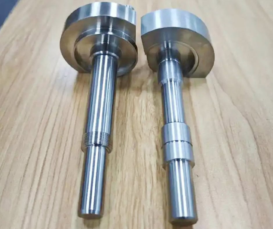
Unlike standard stock shafts, many industrial applications require custom CNC-machined SUS 316L shafts with stepped diameters, precision bearing journals, threaded ends, keyways, cross holes, grooves, or complex locating features. These custom components demand not only high-quality raw material but also precise CNC turning, grinding, dimensional inspection, and surface finishing to achieve reliable assembly performance.
This article explores the engineering applications, selection considerations, and technical characteristics of SUS 316L shafts. It also compares SUS 316L with SUS 304 shafts to help design engineers, procurement professionals, OEM manufacturers, and product developers select the most suitable shaft material for their equipment while balancing corrosion resistance, mechanical performance, manufacturing cost, and long-term reliability.
Table of Contents
Real-World Applications
Marine and Offshore Equipment
Marine environments present one of the most challenging operating conditions for rotating shafts. Continuous exposure to saltwater, humidity, and chloride-rich atmospheres accelerates corrosion, leading to premature failure of conventional steel components. Shafts used in pumps, actuators, winches, and positioning mechanisms must maintain both structural integrity and dimensional accuracy despite these harsh conditions.
SUS 316L shafts are widely adopted because their molybdenum-enhanced alloy composition significantly improves resistance to chloride-induced corrosion compared with standard stainless steels. Precision CNC machining allows bearing journals, sealing surfaces, and threaded sections to be manufactured with tight tolerances, ensuring smooth assembly and reliable operation.
For marine equipment manufacturers, selecting SUS 316L reduces maintenance frequency, extends service intervals, and lowers lifecycle costs by minimizing corrosion-related failures.
Medical Devices and Surgical Equipment
Medical equipment places equally demanding requirements on corrosion resistance, cleanliness, and dimensional precision. Shafts are commonly used in surgical instruments, laboratory automation systems, diagnostic devices, and pharmaceutical manufacturing equipment, where they must withstand repeated sterilization without compromising performance.
The low carbon content of SUS 316L minimizes carbide precipitation during welding or heat exposure, preserving corrosion resistance in critical applications. Precision-ground bearing surfaces and finely machined locating diameters provide smooth motion while maintaining repeatable positioning.
Engineers specify SUS 316L not only for its mechanical performance but also for its proven compatibility with hygienic manufacturing environments where contamination must be minimized.
Food Processing and Packaging Machinery
Food production equipment is regularly exposed to water, cleaning chemicals, and aggressive sanitation procedures. Carbon steel shafts often require protective coatings that can degrade over time, while lower-grade stainless steels may suffer localized corrosion after prolonged exposure.
SUS 316L shafts offer superior resistance to cleaning agents and moisture while maintaining a clean, smooth surface finish that supports hygienic operation. CNC machining enables precise bearing fits, sealing interfaces, and custom drive features without compromising corrosion resistance.
As a result, food equipment manufacturers frequently select SUS 316L to improve equipment longevity and reduce maintenance interruptions.
Semiconductor and Precision Manufacturing Equipment
Semiconductor manufacturing systems rely on micron-level positioning accuracy. Motion stages, wafer handling systems, and precision actuators require shafts with exceptional dimensional consistency and minimal surface defects.
A custom-machined SUS 316L shaft provides accurate bearing journals, concentric diameters, and finely finished sliding surfaces that contribute to stable motion and reduced vibration. Precision grinding following CNC turning further improves roundness and surface quality, ensuring reliable performance in cleanroom environments.
Because contamination control is critical, stainless steel shafts with polished surfaces are preferred over coated carbon steel alternatives that may generate particles during operation.
Chemical Processing Equipment
Chemical processing machinery frequently operates in corrosive environments involving acids, alkalis, or chloride-containing solutions. Rotating shafts in pumps, valves, mixers, and agitators must resist chemical attack while maintaining dimensional stability under continuous loading.
SUS 316L provides excellent corrosion resistance across a broad range of industrial chemicals. When combined with precision machining and appropriate post-processing, these shafts offer long service life even in demanding process environments.
For chemical equipment manufacturers, selecting SUS 316L reduces the likelihood of corrosion-induced shutdowns and improves operational reliability.
Industrial Automation and Robotics
Automation systems incorporate numerous rotating and linear shafts that support actuators, conveyors, robotic joints, and positioning mechanisms. These components must deliver accurate motion while resisting wear under repetitive loading cycles.
Custom CNC-machined SUS 316L shafts allow engineers to integrate stepped diameters, threaded ends, keyways, retaining ring grooves, and precision bearing seats into a single component. This reduces assembly complexity while improving positioning accuracy and overall system reliability.
In automated production environments where equipment operates continuously, durable shaft materials contribute directly to higher productivity and reduced maintenance costs.
Engineering Decision Guide
SUS 316L Shaft vs. SUS 304 Shaft
Among stainless steel shaft materials, SUS 304 and SUS 316L are the two most commonly specified grades. Although both belong to the austenitic stainless steel family and offer excellent corrosion resistance, they differ significantly in chemical composition, mechanical performance, and application suitability. Selecting the appropriate material requires evaluating the operating environment, structural requirements, manufacturing cost, and expected service life.
Engineering Comparison
Comparison Item | SUS 316L Shaft | SUS 304 Shaft |
Corrosion Resistance | Excellent, particularly against chlorides and chemicals | Good for general industrial environments |
Molybdenum Content | Approximately 2–3% | None |
Carbon Content | Lower (≤0.03%) | Higher (≤0.08%) |
Weldability | Excellent with minimal carbide precipitation | Good |
Hygienic Performance | Excellent | Very good |
Typical Material Cost | Higher | Lower |
Typical Applications | Marine, medical, pharmaceutical, chemical processing | General industrial equipment, automation, food processing |
Application Differences
SUS 316L shafts are preferred when equipment operates in environments containing chlorides, saltwater, cleaning chemicals, or corrosive process media. Marine machinery, medical devices, pharmaceutical systems, and chemical processing equipment frequently specify SUS 316L because corrosion resistance directly affects equipment reliability and maintenance requirements.
SUS 304 shafts are commonly used in indoor industrial environments where corrosion exposure is relatively mild. Applications such as automation equipment, conveyors, packaging machinery, and general mechanical assemblies often benefit from the lower material cost while still achieving good corrosion resistance.
Structural Differences
From a structural perspective, both materials can be machined into identical shaft geometries. The primary distinction lies in their metallurgical composition.
The addition of molybdenum in SUS 316L significantly improves resistance to pitting and crevice corrosion. Its lower carbon content also reduces the risk of sensitization after welding or prolonged exposure to elevated temperatures, helping preserve corrosion resistance throughout the component’s service life.
For shafts requiring post-processing to achieve Rm greater than 700 MPa, yield strength above 500 MPa, and hardness exceeding 200 HB, manufacturing process control—including cold working, precision grinding, and surface finishing—is equally important regardless of the stainless steel grade.
Performance Priorities
When corrosion resistance is the highest priority, SUS 316L offers a clear advantage. It performs particularly well in environments where chloride attack, chemical exposure, or frequent cleaning cycles are expected.
However, if the shaft operates in a controlled indoor environment with limited exposure to corrosive substances, SUS 304 often provides sufficient performance at a lower material cost.
Engineers should also consider factors such as fatigue loading, bearing fits, surface finish, and machining tolerances, as these characteristics frequently influence shaft performance as much as material selection.
Cost-Effectiveness
From an initial purchasing perspective, SUS 304 is generally the more economical choice due to its lower alloy content.
Nevertheless, lifecycle cost should also be considered. In corrosive operating environments, premature shaft replacement, unplanned maintenance, and production downtime can quickly outweigh the savings achieved through lower material costs.
Choosing SUS 316L becomes increasingly cost-effective when equipment is expected to operate for many years under demanding environmental conditions. Its superior corrosion resistance often reduces maintenance frequency, extends component service life, and improves overall equipment reliability.
Practical Material Selection Advice
Selecting the right shaft material should always begin with a clear understanding of the operating environment rather than simply comparing material prices.
Choose SUS 316L when:
The shaft operates in marine or coastal environments.
Chloride-containing chemicals are present.
Equipment requires frequent washing or sterilization.
Long-term corrosion resistance is critical.
The application involves medical, pharmaceutical, or chemical processing equipment.
Choose SUS 304 when:
The operating environment is clean and dry.
Corrosion exposure is minimal.
Budget constraints are a primary consideration.
General industrial performance is sufficient.
Ultimately, the most cost-effective solution is not necessarily the least expensive material but the one that delivers the required mechanical performance, corrosion resistance, and service life for the intended application.
Technical Definition & Industry Terminology
Technical Definition
A SUS 316L shaft is a precision-machined cylindrical mechanical component manufactured from SUS 316L austenitic stainless steel. It is primarily designed to transmit torque, support rotating elements, provide accurate positioning, or serve as a structural guide within mechanical assemblies. Depending on the application, the shaft may rotate continuously, oscillate, or remain stationary while supporting bearings, gears, pulleys, couplings, or linear motion components.
Unlike standard ground shaft stock, custom SUS 316L shafts are engineered according to specific functional requirements. Typical features include stepped diameters, precision bearing journals, threaded ends, keyways, retaining ring grooves, cross-drilled holes, splines, and chamfers. These features enable the shaft to integrate seamlessly into complex assemblies while maintaining strict dimensional accuracy.
In most industrial equipment, the shaft acts as the mechanical interface between power transmission components and the machine structure. Its performance directly influences rotational accuracy, vibration levels, bearing life, and overall equipment reliability.
How a SUS 316L Shaft Works
The working principle of a shaft depends on its intended function within the mechanical system.
For power transmission applications, torque generated by a motor or gearbox is transferred through the shaft to gears, pulleys, sprockets, or couplings. The shaft must withstand torsional loads while maintaining concentricity and minimizing deflection.
For positioning or guiding applications, the shaft serves as a precision reference surface for bearings, bushings, or linear bearings. Surface finish, roundness, and dimensional accuracy become critical because they directly affect friction, wear, and positioning repeatability.
In many custom-designed assemblies, a single SUS 316L shaft performs both structural support and torque transmission simultaneously, requiring a careful balance between strength, stiffness, corrosion resistance, and machining precision.
Typical Applications Within an Assembly
A precision SUS 316L shaft may function as:
Drive shaft
Transmission shaft
Support shaft
Spindle shaft
Guide shaft
Roller shaft
Pump shaft
Valve stem
Motor output shaft
Bearing journal shaft
Actuator shaft
Linear guide shaft
Although these components share similar cylindrical geometry, their dimensional tolerances, surface finish requirements, and mechanical loading conditions vary considerably depending on the application.
Common Industry Terminology
Different industries often use different names for similar components. Common English terminology includes:
Stainless Steel Shaft
Precision Shaft
CNC Machined Shaft
Stepped Shaft
Drive Shaft
Transmission Shaft
Guide Shaft
Precision Ground Shaft
Mechanical Shaft
Rotary Shaft
Custom Shaft
Shaft Component
Each term emphasizes a different engineering function. For example, a drive shaft focuses on torque transmission, while a guide shaft primarily provides accurate linear motion support.
Common Abbreviations
Engineering drawings and Bills of Materials (BOMs) frequently use abbreviated identifiers such as:
SS Shaft — Stainless Steel Shaft
PGS — Precision Ground Shaft
DS — Drive Shaft
GS — Guide Shaft
PS — Precision Shaft
These abbreviations are not internationally standardized and should always be interpreted according to project documentation.
Applicable Engineering Standards
Although most SUS 316L shafts are custom-manufactured, their design, material selection, inspection, and tolerancing generally reference internationally recognized standards.
| Standard | Typical Purpose |
| ASTM A276 | Stainless steel bars and shapes |
| ASTM A479 | Stainless steel bars for pressure service |
| JIS G4303 | Stainless steel bars (including SUS316L) |
| ISO 286 | Shaft and hole fits |
| ISO 2768 | General dimensional tolerances |
| ISO 1101 | Geometric Dimensioning and Tolerancing (GD&T) |
| ISO 1302 | Surface texture specification |
| ANSI Y14.5 | GD&T practices |
| DIN 748 | Shaft dimensions and design principles |
When precision bearing fits are required, engineers often specify ISO tolerance classes such as h6, h7, g6, or f7, depending on the required fit between the shaft and mating component.
Performance Explained Through Manufacturing
The performance of a SUS 316L shaft is determined by far more than the material itself. Precision machining, heat treatment or cold-working processes, grinding, surface finishing, and inspection all contribute to the shaft’s mechanical properties, dimensional accuracy, and long-term reliability. Manufacturing quality ultimately determines whether the shaft performs consistently under real operating conditions.
High Mechanical Strength
Although SUS 316L is widely recognized for corrosion resistance, many industrial applications also require enhanced mechanical strength. Through appropriate material processing and post-treatment, custom shafts can achieve tensile strength greater than 700 MPa, yield strength above 500 MPa, and hardness exceeding 200 HB, making them suitable for demanding mechanical applications.
High-strength performance begins with selecting certified raw materials and controlling deformation throughout machining. Cold working or specialized strengthening processes are often incorporated before finish machining to achieve the specified mechanical properties without sacrificing corrosion resistance.
Mechanical properties are verified through tensile testing and hardness testing before production release.
Precision Dimensional Accuracy
Bearing journals, seal diameters, and locating shoulders require exceptional dimensional consistency. Even slight dimensional deviations may reduce bearing life or create excessive assembly preload.
Rough turning is typically followed by semi-finishing and precision CNC turning. Critical diameters are then finished through cylindrical grinding to achieve tight dimensional tolerances, excellent roundness, and superior concentricity.
Coordinate Measuring Machine (CMM) inspection, micrometers, air gauges, and dial indicators verify critical dimensions before shipment.
Corrosion Resistance
One of the primary advantages of SUS 316L is its resistance to chloride-induced corrosion, chemical attack, and humid operating environments.
Maintaining this corrosion resistance depends on proper manufacturing practices. Excessive cutting temperatures, embedded carbon steel contamination, or improper post-processing can compromise the passive oxide layer.
Following machining, shafts are commonly subjected to passivation, ultrasonic cleaning, and polishing to restore surface cleanliness and maximize corrosion resistance.
Surface condition is verified through visual inspection, cleanliness inspection, and, where required, passivation verification.
Wear Resistance
Although stainless steel is not inherently as wear-resistant as hardened alloy steel, carefully controlled surface finishing significantly improves its tribological performance.
Precision grinding reduces surface irregularities while polishing minimizes friction between the shaft and mating bearings or bushings. For specialized applications, additional surface treatments such as hard chrome plating, PVD coatings, or low-temperature nitriding may be considered where compatible with corrosion requirements.
Surface roughness testing ensures that bearing journals meet specified Ra values, typically ranging from Ra 0.2–0.8 μm depending on the application.
Fatigue Resistance
Many industrial shafts experience millions of load cycles during their operational life. Fatigue performance therefore depends heavily on eliminating stress concentrations and machining defects.
Generous fillet radii between stepped diameters reduce localized stresses. Fine surface finishes minimize crack initiation sites, while precision machining eliminates tool marks that could accelerate fatigue failure.
Critical shafts may undergo magnetic particle inspection or dye penetrant testing to detect surface defects before delivery.
Assembly Reliability
Successful assembly depends on more than dimensional accuracy alone. Thread quality, concentricity, shoulder squareness, and bearing fits all influence installation efficiency and long-term performance.
Precision drilling, tapping, thread milling, and chamfering ensure consistent engagement of fasteners and mating components. Functional gauges verify threaded features, while runout measurements confirm rotational accuracy.
Reliable assembly minimizes installation adjustments and contributes to consistent equipment performance across production batches.
Manufacturing Challenges
Producing a high-quality SUS 316L shaft involves several manufacturing challenges:
Controlling heat generation during machining to prevent work hardening.
Maintaining concentricity across multiple machining operations.
Achieving precise bearing fits while minimizing residual stresses.
Preventing distortion during long, slender shaft machining.
Controlling surface roughness after grinding and polishing.
Maintaining straightness throughout production.
Protecting finished surfaces during handling and packaging.
Addressing these challenges requires optimized tooling, stable machining parameters, rigid fixturing, and comprehensive quality control throughout the manufacturing process.
Design Considerations & Engineering Best Practices
Designing a SUS 316L shaft requires balancing mechanical performance, corrosion resistance, manufacturability, and cost. While material selection is important, the shaft’s geometry, tolerances, and interface design ultimately determine how effectively it performs within the mechanical assembly.
Load Analysis and Shaft Diameter Selection
The first step in shaft design is understanding the loads the component will experience during operation. Engineers should evaluate torsional loads, bending moments, axial forces, and combined loading conditions before determining the shaft diameter.
In most industrial applications, selecting the minimum possible diameter to reduce material cost is not recommended. A slightly larger shaft often provides significantly greater stiffness, reduces deflection, and improves bearing alignment.
Bearing Journal Design
Bearing journals are among the most critical functional features of any shaft. Their diameter, surface finish, and concentricity directly influence bearing performance and service life.
When specifying bearing seats, engineers should select appropriate ISO fit classes based on the bearing manufacturer’s recommendations. Overly tight fits may generate excessive preload, while loose fits can allow unwanted movement during operation.
Stress Concentration Reduction
A common design mistake is introducing sharp transitions between shaft diameters.
Sharp shoulders create localized stress concentrations that significantly reduce fatigue life. Instead, generous fillet radii or relief grooves should be incorporated wherever possible to distribute stresses more evenly.
If space limitations require small transition radii, finite element analysis (FEA) can help identify potential high-stress regions before production begins.
Tolerance Selection
Not every shaft feature requires ultra-tight tolerances.
Critical functional surfaces—such as bearing journals, sealing diameters, and locating shoulders—should receive tighter dimensional control, while non-functional dimensions can often follow general tolerances.
Applying unnecessarily restrictive tolerances increases machining time, inspection requirements, and production cost without improving overall equipment performance.
Surface Finish Requirements
Surface finish should always match the intended function of each shaft section.
Bearing journals typically require fine ground finishes, whereas threaded sections, wrench flats, or non-contact surfaces may not require additional finishing operations.
Over-specifying mirror-polished surfaces across the entire shaft is a common design mistake that increases manufacturing cost without providing measurable engineering benefits.
Corrosion Protection Strategy
Although SUS 316L offers excellent corrosion resistance, design details can still influence long-term durability.
Engineers should avoid creating narrow crevices where moisture or chemicals may become trapped. Drainage features, smooth transitions, and accessible cleaning surfaces improve corrosion performance in sanitary and chemical-processing applications.
Where dissimilar metals are assembled together, consideration should also be given to preventing galvanic corrosion through material compatibility or electrical isolation.
Design for Manufacturability (DFM)
Effective DFM reduces production cost while maintaining engineering performance.
Whenever possible, designers should:
Standardize thread sizes.
Minimize unnecessary diameter changes.
Avoid excessively deep blind holes.
Specify realistic tolerances.
Simplify groove geometries.
Reduce the number of machining setups.
Early collaboration between design engineers and CNC manufacturing engineers often results in shorter lead times, improved machining efficiency, lower inspection costs, and greater production consistency.
By integrating sound engineering principles with practical manufacturing considerations, a well-designed SUS 316L shaft delivers reliable performance, excellent corrosion resistance, and long service life across a wide range of industrial applications.
Failure Analysis, Troubleshooting & Maintenance
Although a SUS 316L shaft offers excellent corrosion resistance and reliable mechanical performance, its service life depends heavily on proper design, manufacturing quality, installation, and maintenance. In practice, shaft failures are rarely caused by the material itself. Most problems originate from misalignment, improper bearing fits, overload, poor lubrication, or assembly errors. Understanding these common failure modes helps engineers improve equipment reliability while minimizing unplanned downtime.
Shaft Misalignment
Symptoms
Excessive vibration during operation
Abnormal bearing noise
Increased operating temperature
Premature bearing failure
Uneven wear on couplings or seals
Root Cause
Misalignment typically results from inaccurate installation, frame deformation, worn bearings, or machining errors in mating components. Even a small angular or parallel offset can generate significant additional loading on the shaft and bearings.
Engineering Analysis
When a shaft operates under misalignment, bending stress is continuously introduced into the rotating assembly. This additional stress accelerates fatigue, increases bearing loads, and reduces rotational efficiency. In high-speed applications, misalignment also contributes to imbalance and vibration.
Corrective Action
Verify shaft alignment using dial indicators or laser alignment systems.
Inspect bearing housings for dimensional accuracy.
Replace damaged bearings or worn couplings.
Reassemble according to the equipment manufacturer’s alignment procedure.
Preventive Measures
Perform alignment verification during installation.
Maintain proper foundation rigidity.
Inspect alignment after major maintenance or equipment relocation.
Periodically monitor vibration trends during operation.
Bearing Journal Wear
Symptoms
Increased radial clearance
Bearing looseness
Reduced rotational accuracy
Surface scoring or polishing marks
Difficulty maintaining bearing preload
Root Cause
Bearing journal wear is commonly caused by insufficient lubrication, contamination, improper bearing fit, or extended service under heavy loads.
Engineering Analysis
As the journal diameter gradually decreases, bearing interference is reduced, allowing micro-movement between the bearing and shaft. This movement accelerates wear and eventually compromises machine accuracy.
Corrective Action
Measure journal diameters using calibrated micrometers.
Compare measurements with design tolerances.
Replace or repair shafts exceeding allowable wear limits.
Replace damaged bearings simultaneously.
Preventive Measures
Maintain proper lubrication intervals.
Prevent contamination from entering bearing assemblies.
Verify bearing fits during equipment overhaul.
Use appropriate shaft hardness and surface finish for the application.
Corrosion and Surface Pitting
Symptoms
Localized pitting
Surface discoloration
Rough bearing or sealing surfaces
Increased friction
Seal leakage
Root Cause
Although SUS 316L offers excellent corrosion resistance, prolonged exposure to concentrated chlorides, aggressive acids, or contaminated surfaces may eventually initiate localized corrosion. Improper cleaning after machining can also leave iron contamination that promotes rust staining.
Engineering Analysis
Surface pitting creates localized stress concentrations that may reduce fatigue strength. Corrosion on sealing surfaces also accelerates seal wear and increases leakage risk.
Corrective Action
Clean affected surfaces thoroughly.
Perform passivation if appropriate.
Replace shafts exhibiting deep pitting in functional areas.
Investigate the operating environment for unexpected chemical exposure.
Preventive Measures
Specify passivation after machining.
Avoid contamination from carbon steel tooling.
Select compatible sealing materials.
Follow recommended cleaning procedures for stainless steel equipment.
Fatigue Cracking
Symptoms
Fine cracks near shoulders or keyways
Sudden shaft fracture after prolonged service
Increasing vibration before failure
Visible crack propagation during inspection
Root Cause
Fatigue failures generally result from repeated cyclic loading combined with stress concentrations at sharp corners, keyways, threads, or machining defects.
Engineering Analysis
Fatigue cracks normally initiate at the surface, where tensile stresses are highest. As loading continues, cracks propagate until the remaining cross-sectional area can no longer support the applied load.
Corrective Action
Remove the failed shaft from service immediately.
Perform fracture analysis to determine the origin of the crack.
Redesign high-stress features if repeated failures occur.
Preventive Measures
Increase fillet radii at diameter transitions.
Improve surface finish.
Avoid machining marks perpendicular to the stress direction.
Validate designs using Finite Element Analysis (FEA).
Excessive Runout
Symptoms
Rotational wobble
Poor machining accuracy
Uneven seal wear
High spindle vibration
Reduced positioning precision
Root Cause
Runout may be caused by improper machining, shaft distortion during heat treatment or post-processing, incorrect chucking methods, or impact damage during transportation.
Engineering Analysis
Even minor runout increases dynamic loading and reduces bearing life. In precision equipment such as semiconductor machinery or medical devices, excessive runout may significantly affect overall system accuracy.
Corrective Action
Measure total indicated runout (TIR) using a dial indicator.
Verify straightness and concentricity.
Replace shafts outside specification.
Review machining and fixturing methods.
Preventive Measures
Use precision grinding after CNC turning.
Support long shafts with steady rests during machining.
Protect finished shafts with dedicated packaging during transport.
Thread Damage
Symptoms
Difficulty assembling fasteners
Cross-threading
Loose retaining nuts
Thread galling
Root Cause
Improper installation, excessive tightening torque, inadequate lubrication, or poor thread quality.
Engineering Analysis
Damaged threads reduce clamping force and may eventually require complete shaft replacement, particularly when threads are integral to the shaft.
Corrective Action
Inspect thread profiles using thread gauges.
Repair minor damage where permitted.
Replace severely damaged shafts.
Preventive Measures
Apply correct tightening torque.
Use compatible fastener materials.
Lubricate stainless steel threads to reduce galling.
Protect threaded ends during transportation.
Recommended Preventive Maintenance
Although SUS 316L shafts require relatively little maintenance, periodic inspection significantly improves equipment reliability.
Recommended maintenance activities include:
Verify shaft alignment during scheduled maintenance.
Inspect bearing journals for wear.
Measure shaft runout periodically.
Clean corrosion deposits promptly.
Check threaded sections for damage.
Replace worn bearings before they damage the shaft.
Maintain lubrication according to equipment specifications.
Record inspection results to identify long-term performance trends.
A proactive maintenance program generally reduces downtime and extends both shaft and bearing service life.
Purchasing Considerations & RFQ Guide
Selecting a supplier for precision SUS 316L shafts involves evaluating much more than machining capability. Material traceability, process control, inspection standards, and post-processing quality all contribute to the final performance of the component. Engineers and procurement professionals should assess suppliers based on their ability to consistently manufacture shafts that meet both dimensional and mechanical requirements.
Factors Affecting Manufacturing Cost
Several engineering and production variables influence the total manufacturing cost of a SUS 316L shaft.
| Cost Factor | Engineering Impact |
| Material Grade | Certified SUS 316L bar stock with full traceability typically costs more than general commercial material. |
| Shaft Geometry | Stepped diameters, long slender designs, deep grooves, and complex threads increase machining time. |
| CNC Machining Time | Multiple setups, tight concentricity requirements, and secondary operations increase production costs. |
| Precision Grinding | Bearing journals and sealing surfaces often require cylindrical grinding after turning. |
| Post-Processing | Passivation, polishing, stress relief, or strengthening treatments add manufacturing steps. |
| Tolerance Requirements | Tight ISO fits require additional machining and inspection. |
| Inspection Reports | CMM reports, hardness testing, and material certificates increase quality assurance costs. |
| Order Quantity | Larger production volumes reduce unit costs through process optimization. |
| Packaging | Protective packaging prevents surface damage during transportation, especially for polished shafts. |
The most economical solution is not necessarily the lowest-priced component. Consistent machining quality often reduces assembly time, minimizes field failures, and lowers the total cost of ownership.
Available Manufacturing Options
Standard Shaft Stock
Standard stainless steel shafts are suitable for applications requiring simple diameters and readily available dimensions. They offer short lead times but limited customization.
Custom CNC Machined Shafts
Most OEM equipment requires custom shaft designs incorporating bearing journals, keyways, threads, grooves, cross holes, or splines. CNC turning, milling, drilling, and grinding enable these features to be produced with high precision while maintaining excellent concentricity.
Prototype Production
Prototype manufacturing allows engineers to verify dimensions, assembly fit, and functional performance before committing to larger production quantities. Early prototype validation helps identify design improvements while minimizing development costs.
Low-Volume Manufacturing
Low-volume production is ideal for specialized machinery, replacement parts, pilot production, and customized industrial equipment where flexibility is more important than maximum production efficiency.
High-Volume Production
For production programs involving hundreds or thousands of shafts, dedicated fixtures, optimized CNC programs, automatic inspection, and statistical process control improve consistency while reducing unit costs.
RFQ Preparation Guide
Providing complete engineering documentation allows suppliers to evaluate manufacturability accurately and prepare reliable quotations.
A professional RFQ should include:
2D engineering drawings (PDF)
3D CAD files (STEP, STP, IGES, Parasolid, SolidWorks, etc.)
Material specification (SUS 316L)
Mechanical property requirements
-Tensile strength (Rm > 700 MPa)
-Yield strength (> 500 MPa)
-Hardness (> 200 HB)
Surface roughness requirements
Heat treatment or strengthening requirements
Passivation or polishing specifications
ISO fit requirements
Critical GD&T features
Required quantity
Inspection requirements
Material certificates
Packaging requirements
Delivery schedule
Complete technical documentation minimizes quotation delays and helps prevent manufacturing errors.
Questions to Ask Your CNC Machining Supplier
Before placing an order, engineers should evaluate a supplier’s technical capability by asking questions such as:
Can you provide certified SUS 316L material with full traceability?
What shaft diameter and length range can you machine?
Can you achieve ISO h6 or tighter tolerances?
Is cylindrical grinding available in-house?
Can you provide tensile strength, hardness, and material certification reports?
Do you perform 100% inspection on critical dimensions?
How do you control straightness and concentricity during production?
Can prototype samples be supplied before mass production?
A technically capable supplier should be able to answer these questions with documented manufacturing and quality control procedures rather than general statements.
Frequently Asked Questions
What are the main advantages of a SUS 316L shaft?
SUS 316L shafts offer excellent corrosion resistance, good mechanical properties, outstanding weldability, and reliable performance in demanding environments. They are widely used in marine equipment, medical devices, food processing machinery, and chemical processing systems where long-term durability is essential.
Why choose SUS 316L instead of carbon steel?
Carbon steel generally provides higher hardness after heat treatment but requires protective coatings to resist corrosion. SUS 316L naturally resists corrosion without additional coating, making it a better choice for humid, sanitary, or chemically aggressive environments where maintenance costs and cleanliness are important considerations.
Can SUS 316L shafts be customized?
Yes. Most industrial shafts are custom-machined according to customer drawings. Common features include stepped diameters, bearing journals, keyways, splines, threaded ends, cross holes, retaining ring grooves, and precision-ground sealing surfaces.
What machining tolerances can be achieved?
Typical CNC turning can achieve tolerances around ±0.01 mm, while precision grinding allows tighter dimensional control on critical bearing journals and sealing surfaces. Actual tolerances depend on shaft size, geometry, and application requirements.
What information is required for a quotation?
A complete RFQ should include 2D drawings, 3D CAD models, material specifications, mechanical property requirements, surface finish, tolerances, quantity, inspection requirements, and any applicable certification requests. Providing detailed engineering documentation helps suppliers prepare accurate quotations and manufacturing plans.
What is the typical production lead time?
Lead time varies depending on shaft complexity, order quantity, material availability, post-processing, and inspection requirements. Prototype shafts are commonly delivered within 1–2 weeks, while production orders generally require 2–5 weeks, depending on project scope and manufacturing capacity.