Product Overview
A Triple-Frequency Voltage Block is a specialized component used in electrical systems where voltage behavior at a third-harmonic or triple-frequency condition must be controlled, isolated, supported, or mechanically integrated into a larger assembly. Unlike a general-purpose electrical enclosure or mounting block, its design is normally driven by the electrical architecture, insulation requirements, mechanical interfaces, and the operating environment of the final system.
The exact configuration of a Triple-Frequency Voltage Block can vary considerably depending on the equipment in which it is installed. In some systems, the component primarily provides a mechanically stable interface for electrical elements. In others, it can form part of an assembly designed to manage voltage distribution, isolation, harmonic-related electrical behavior, or the positioning of conductive and insulating elements.
This distinction is important when sourcing the component. There is rarely a single universal geometry or specification that applies to every Triple-Frequency Voltage Block. Dimensions, mounting features, material selection, insulation requirements, hole patterns, surface treatment, and tolerances should therefore be established from the customer’s drawing and application requirements.
What Does a Triple-Frequency Voltage Block Do?
At a system level, the component is intended to support controlled voltage operation where a triple-frequency component is present or where electrical isolation and mechanical positioning are required.
A well-designed block can help address several engineering problems:
Maintaining accurate positioning between electrical components
Providing a rigid mechanical mounting interface
Maintaining required electrical clearances and creepage distances
Preventing unwanted movement caused by vibration
Supporting thermal and environmental requirements
Providing repeatable assembly and replacement
Integrating custom hole patterns, locating features, threads, and mounting surfaces
The term “triple-frequency” should not automatically be interpreted as a universal operating frequency or voltage rating. These parameters depend on the electrical system and should be defined according to the application rather than assumed from the component name.
Typical Structure
Depending on the design, a Triple-Frequency Voltage Block may include:
A machined main body
Mounting holes or threaded holes
Counterbores or countersinks
Locating features
Recesses or pockets
Flat reference surfaces
Slots for adjustment or installation
Interfaces for conductive or insulating components
The geometry is often relatively compact, but apparently simple blocks can require tight control of several surfaces simultaneously.
Common materials include aluminum alloys, stainless steel, engineering plastics, and other electrically or mechanically appropriate materials. The correct choice depends on whether the primary requirement is structural rigidity, low mass, electrical insulation, thermal management, corrosion resistance, or a combination of these properties.
Table of Contents
Design & Performance
The engineering value of a Triple-Frequency Voltage Block is determined less by its external appearance than by how accurately it performs its mechanical and electrical role inside the complete assembly.
1. Dimensional Accuracy
Dimensional accuracy is fundamental when the block interfaces with other electrical or mechanical components.
A hole that is slightly displaced can create assembly problems, while an incorrectly machined reference surface can affect the position of connected components. For assemblies with multiple interfaces, individual dimensional errors can accumulate and create a noticeable final offset.
Critical dimensions should therefore be identified from the drawing rather than applying unnecessarily tight tolerances to every feature.
2. Positioning and Hole Accuracy
Mounting-hole position can be particularly important when the block is installed between several components.
Hole locations may determine:
Component alignment
Fastener engagement
Connector positioning
Electrical spacing
Interchangeability
Assembly repeatability
For complex hole patterns, CNC machining provides a controlled coordinate system that allows multiple features to be produced from common datums.
3. Flatness and Parallelism
Reference surfaces often determine how the block sits against adjacent components.
Poor flatness can introduce gaps, rocking, uneven fastening, or misalignment. Parallelism becomes important when two opposing surfaces establish the position of another component.
These characteristics should be controlled according to functional requirements rather than specified arbitrarily. A tighter tolerance generally increases machining and inspection requirements.
4. Electrical Clearance and Isolation
Where the block forms part of a voltage-related assembly, physical geometry can influence electrical isolation.
Clearances, recesses, material selection, and the arrangement of conductive components may all affect the electrical design. The mechanical manufacturer should therefore work from the customer’s electrical and mechanical requirements rather than assuming that a generic block geometry is suitable.
If the component is manufactured from an insulating material, material properties and environmental conditions also need to be considered.
5. Thermal Stability
Electrical assemblies can experience temperature changes during operation. Differences in thermal expansion between the block and adjacent components may affect alignment or mechanical stress.
Material selection therefore becomes more than a question of strength.
For example:
Aluminum can provide low weight and good thermal conductivity.
Stainless steel offers higher corrosion resistance and mechanical robustness.
Engineering plastics can provide electrical insulation and low weight.
Specialized materials may be selected when temperature, dielectric, or chemical requirements demand them.
The appropriate solution depends on the complete assembly.
6. Vibration Resistance
Components used inside industrial electrical equipment may experience vibration from motors, fans, pumps, switching equipment, or transportation.
A suitable block should maintain its dimensional relationship with mating components throughout its service environment. Thread engagement, mounting geometry, wall thickness, and material stiffness all contribute to mechanical stability.
7. Surface Quality and Long-Term Reliability
Surface condition affects more than appearance.
A controlled surface finish can improve contact between mating parts, reduce the risk of burr-related assembly problems, and provide a suitable base for anodizing, plating, painting, or other treatments.
For conductive components, the surface treatment must also be compatible with the intended electrical function. A coating that electrically isolates a surface may be unsuitable if that surface is intended to provide electrical continuity.
Materials & Design Options
Material selection should begin with the functional requirements of the assembly.
| Material | Main Advantages | Typical Considerations |
| Aluminum alloy | Lightweight, machinable, good thermal conductivity | Lower stiffness than many steels; surface treatment may be required |
| Stainless steel | Corrosion resistance, strength, durability | Higher machining cost and cutting forces |
| Carbon steel | High strength and relatively economical | Usually requires corrosion protection |
| Engineering plastic | Electrical insulation, low weight, good machinability | Thermal expansion and mechanical strength depend on grade |
| Specialty insulating material | Designed for demanding electrical environments | Material cost and machining requirements can be higher |
Fixed vs. Adjustable Designs
A fixed Triple-Frequency Voltage Block is appropriate when the assembly geometry is established and repeatability is more important than adjustment.
An adjustable version may incorporate slots or positioning features where installation tolerances need to be accommodated.
Adjustment features can make installation easier, but they also increase machining complexity and may introduce additional movement or tolerance considerations.
Standard vs. Custom
Standard components can be economical when their dimensions and interfaces match the application.
Custom machining becomes more appropriate when the customer requires:
A non-standard mounting pattern
Specific overall dimensions
Special material
Controlled reference surfaces
Custom recesses or pockets
Special threads
Integration with an existing assembly
For B2B equipment manufacturers, a drawing-based custom component is often more practical than modifying a standard part to approximate the required geometry.
Lightweight vs. Reinforced Design
Material can often be removed from non-critical regions through pockets or reduced wall sections.
However, lightweighting should not compromise:
Mounting strength
Thread depth
Structural stiffness
Electrical spacing
Thermal behavior
Assembly durability
The best geometry is therefore not necessarily the one with the least material. It is the one that provides the required functionality without unnecessary manufacturing complexity.
Manufacturing & CNC Machining
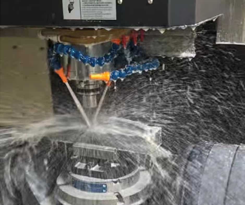
CNC machining is well suited to custom Triple-Frequency Voltage Blocks because the process can combine multiple dimensional features in a controlled coordinate system.
A typical manufacturing sequence may include:
1.Material preparation
2.CNC milling or turning where applicable
3.Drilling and tapping
4.Reaming for critical holes
5.Secondary multi-axis machining where required
6.Deburring
7.Cleaning
8.Surface treatment
9.Dimensional inspection
10.Final packaging
CNC Milling
CNC milling is commonly used for block-shaped components.
It can produce:
Flat surfaces
Steps
Pockets
Slots
Counterbores
Countersinks
Threaded holes
Complex external profiles
Three-axis machining may be sufficient for relatively simple geometries. Additional-axis machining can become useful when several faces or difficult-to-access features must be machined while maintaining positional relationships.
Drilling, Tapping and Reaming
Hole-making operations require particular attention when holes serve as locating or mounting interfaces.
Drilled holes may be sufficient for clearance applications, while tapped holes require appropriate thread depth and tool control. Reaming can be used when a more controlled hole size or fit is required.
Three Manufacturing Challenges
1. Maintaining Multiple Datums
A block may have several functional surfaces that establish the position of other components.
If the part is repositioned unnecessarily between operations, accumulated setup errors can affect hole positions and surface relationships.
Solution: use stable datums, minimize unnecessary repositioning, and establish the machining sequence around the most important functional features.
2. Machining Thin Walls and Recesses
Lightweight designs may include pockets or thin sections. Removing too much material can increase vibration during machining and cause dimensional variation.
Solution: select appropriate cutting parameters, tooling, workholding, and machining sequences. Where necessary, critical finishing passes should be performed after roughing operations have released internal stresses.
3. Controlling Burrs Around Electrical Interfaces
Burrs around holes, slots, or edges can interfere with assembly and may be particularly undesirable around electrical interfaces.
Solution: use controlled cutting conditions followed by appropriate deburring and cleaning. Critical edges should be defined on the drawing rather than relying on an assumed universal edge condition.
4. Protecting Surface Finish
Reference surfaces can be damaged during secondary operations, inspection, or handling.
Solution: establish suitable workholding methods, protect finished surfaces during subsequent processing, and define cosmetic or functional surface requirements clearly.
5. Maintaining Hole Position Across Multiple Faces
When holes exist on several faces, the relationship between those features can be more important than the individual hole diameter.
Solution: use appropriate datum structures and, where necessary, multi-axis machining or controlled secondary setups to preserve feature-to-feature accuracy.
Quality Control
Quality control should be based primarily on the customer’s engineering drawing and functional requirements.
A typical inspection plan may include:
Overall dimensions
Critical thicknesses
Hole diameter
Hole position
Thread dimensions
Flatness
Parallelism
Perpendicularity
Surface finish
Edge and burr condition
Functional fit
For straightforward parts, calibrated measuring tools may be sufficient. More demanding geometries may require a coordinate measuring machine (CMM) or other precision inspection equipment.
Why Drawing-Based Inspection Matters
A Triple-Frequency Voltage Block does not necessarily have one universal tolerance specification.
For example, one application may require a particularly accurate hole pattern, while another may place greater importance on flatness or electrical clearance.
The correct approach is therefore to identify the critical-to-function characteristics on the customer’s drawing and inspect them accordingly.
This also prevents unnecessary cost. Applying extremely tight tolerances to non-functional features can increase machining time, tool requirements, inspection effort, and scrap risk without improving the final assembly.
Applications
The exact use of a Triple-Frequency Voltage Block depends on its electrical architecture and mechanical configuration. Potential applications include specialized power-electronics and electrical equipment where controlled voltage behavior, mechanical positioning, or isolation is required.
1. Power Conversion Equipment
Power conversion systems can contain multiple electrical components that require accurate mechanical positioning.
A custom-machined block can provide a stable interface while accommodating the specific geometry of the equipment.
2. Electrical Test and Measurement Equipment
Test equipment often requires repeatable component positioning and controlled interfaces.
Custom dimensions can be important when the block forms part of a fixture, measurement assembly, or specialized electrical module.
3. Industrial Power Systems
Industrial electrical equipment may operate under vibration, temperature variation, and demanding environmental conditions.
The block must therefore be designed around mechanical stability, material compatibility, and the requirements of the complete electrical assembly.
4. Transformer and Harmonic-Related Equipment
Triple-frequency or third-harmonic voltage phenomena occur in certain three-phase electrical systems. Third-harmonic voltages can appear in specific transformer and generator configurations, particularly in relation to neutral points and magnetic behavior.
In such equipment, a mechanically precise component may form part of a specialized assembly intended to manage or interface with these electrical conditions.
5. Custom OEM Electrical Assemblies
OEM equipment manufacturers may require a component that cannot be purchased as an off-the-shelf item.
Custom CNC manufacturing allows the geometry, material, mounting pattern, and surface treatment to be matched to the OEM assembly.
Triple-Frequency Voltage Block vs. Conventional Mounting Block
A conventional mounting block can provide mechanical support, but it is not necessarily designed around the electrical and system-level considerations associated with a voltage-related application.
| Factor | Triple-Frequency Voltage Block | Conventional Mounting Block |
| Application | Specialized electrical or power equipment | General mechanical mounting |
| Design focus | Mechanical positioning plus application-specific electrical requirements | Primarily mechanical support |
| Material selection | May depend on insulation, thermal and electrical requirements | Usually based on mechanical requirements |
| Geometry | Often application-specific | May be standardized |
| Inspection | Functional dimensions and interfaces may be critical | Usually focused on mechanical dimensions |
| Manufacturing | CNC machining may require multiple controlled setups | Often simpler |
| Cost | Can be higher due to customization and inspection | Generally lower for simple geometries |
When Should Buyers Choose Each?
Choose a Triple-Frequency Voltage Block when the component is part of a specialized voltage-related assembly and its geometry, material, or interfaces need to be engineered around that application.
Choose a conventional mounting block when the primary requirement is simply mechanical support and there are no special electrical, insulation, thermal, or positional constraints.
The difference is therefore not simply the shape of the component. It is the function it performs within the complete system.
Cost & Procurement
The cost of a custom Triple-Frequency Voltage Block is determined by the manufacturing requirements rather than the product name alone.
Key cost factors include:
Material
Material price varies significantly between aluminum, stainless steel, steel, engineering plastics, and specialty materials.
The most expensive material is not necessarily the best choice. Material should be selected according to mechanical, electrical, thermal, environmental, and regulatory requirements.
Complexity
A simple rectangular block with several drilled holes is relatively straightforward.
Pockets, angled surfaces, compound profiles, thin walls, difficult-to-access features, and multiple machining orientations increase programming, setup, and machining time.
Tolerance
Tighter tolerances generally require more controlled machining and inspection.
A practical drawing should distinguish between functional dimensions and non-critical dimensions.
Quantity
Prototype quantities usually have a higher unit cost because setup and programming expenses are distributed across fewer parts.
Low-volume production can provide a useful balance between engineering flexibility and repeatability.
For OEM production, optimized tooling, workholding, inspection procedures, and machining sequences can reduce the unit cost as volume increases.
Surface Treatment
Anodizing, plating, passivation, painting, powder coating, or other treatments can add both processing cost and lead time.
The selected treatment should be compatible with the material and the intended electrical function of the finished part.
Inspection Requirements
Basic dimensional inspection is different from comprehensive inspection involving CMM measurement, material certification, detailed reports, or additional process controls.
Buyers should specify the inspection level they actually need.
Prototype, Low-Volume, OEM and Production Sourcing
Prototype
Prototype machining is appropriate when the design is still being validated.
At this stage, buyers may prioritize speed and design flexibility over the lowest unit cost.
Low-Volume Production
Low-volume manufacturing is suitable when equipment demand is limited or the product is still entering the market.
The manufacturer can maintain drawing control and repeatability without requiring high-volume production quantities.
OEM Manufacturing
OEM sourcing is appropriate when the Triple-Frequency Voltage Block is an integrated part of a larger product.
Drawing revision control, repeatability, inspection documentation, packaging, and supply continuity become increasingly important.
Production Manufacturing
For recurring production, manufacturing engineering becomes as important as the initial machining process.
Tool selection, fixture design, process sequencing, inspection plans, and batch control can all influence long-term cost and consistency.
Customization & Quotation
A custom Triple-Frequency Voltage Block can typically be manufactured according to the customer’s mechanical drawing and application requirements.
Possible customization includes:
Overall dimensions
Hole patterns
Thread types
Counterbores and countersinks
Slots
Pockets
Locating features
Material
Surface finish
Surface treatment
Edge conditions
Inspection requirements
Packaging requirements
For an accurate quotation, buyers should normally provide:
2D engineering drawing
3D CAD file, preferably in a commonly supported format
Material specification
Required quantity
Dimensional tolerances
Surface finish requirements
Surface treatment
Inspection requirements
Any special assembly or functional requirements
A 3D CAD model defines the geometry, but the 2D drawing normally remains essential for manufacturing because it establishes tolerances, datums, surface requirements, threads, and other manufacturing-critical information.
FAQs
1. What is a Triple-Frequency Voltage Block used for?
A Triple-Frequency Voltage Block is a specialized component used in voltage-related electrical or power equipment where controlled mechanical positioning, electrical isolation, interface geometry, or other application-specific requirements are important. Its exact function depends on the system design.
2. What materials can be used for a Triple-Frequency Voltage Block?
Common options can include aluminum alloys, stainless steel, carbon steel, engineering plastics, and specialized insulating materials. The correct material depends on strength, weight, thermal behavior, electrical requirements, corrosion resistance, and the operating environment.
3. Can a Triple-Frequency Voltage Block be custom machined?
Yes. Custom CNC machining is appropriate when the component requires a non-standard shape, hole pattern, material, tolerance, surface treatment, or interface. The final configuration should be manufactured according to the customer’s engineering drawing.
4. How precise can CNC machining be for this component?
The achievable precision depends on material, geometry, machine configuration, feature size, tolerance requirements, and production process. Rather than assuming a universal accuracy value, critical tolerances should be specified on the drawing and evaluated according to the actual design.
5. Does the component need surface treatment?
Not necessarily. Surface treatment depends on the material and application. Aluminum may be anodized for specific surface or environmental requirements, while stainless steel may require a different finishing approach. For electrically functional surfaces, the effect of the treatment on conductivity or insulation must also be considered.
6. What information should I provide when requesting a quotation?
The most useful information is a 2D drawing, 3D CAD model, material, quantity, critical tolerances, surface finish, surface treatment, and inspection requirements. If the component has a specific electrical or assembly function, providing that context can also help the manufacturer identify critical features.
Conclusion
A Triple-Frequency Voltage Block should be treated as an engineered component rather than a generic machined block. Its performance depends on how mechanical geometry, material properties, electrical requirements, thermal behavior, and manufacturing processes interact within the final assembly.
The most important considerations are usually not simply overall dimensions. Hole position, reference-surface accuracy, flatness, material compatibility, electrical clearance, vibration resistance, and surface condition can all influence the reliability of the finished system.
For custom production, CNC milling provides the flexibility needed to manufacture complex mounting features, pockets, holes, threads, and precision interfaces. However, good machining alone does not guarantee a suitable component. The manufacturing process must begin with a clear understanding of the customer’s functional requirements and drawing.
For engineers and procurement teams, the most effective sourcing strategy is therefore to define the application first, identify critical-to-function features, select a suitable material, and then establish the appropriate machining and inspection process. Whether the requirement is a prototype, low-volume OEM component, or recurring production part, a drawing-based manufacturing approach provides the clearest path to consistent quality and predictable cost.