Product Overview
Magnetic bearing spindles are high-speed rotating spindle systems that use magnetic forces to support a rotating shaft without conventional mechanical contact at the primary bearing locations. Unlike conventional spindle systems that rely on rolling-element or fluid-film bearings, magnetic bearing technology can maintain rotor position while minimizing mechanical contact, friction, and wear.
This architecture is particularly valuable where high rotational speed, low vibration, cleanliness, or long operating periods are important. Instead of relying on physical bearing surfaces to carry the rotating shaft, magnetic bearings use controlled electromagnetic forces to maintain the rotor within a defined operating position.
A typical magnetic bearing spindle can contain:
Rotor and spindle shaft
Radial magnetic bearing assemblies
Axial magnetic bearing or thrust-control system
Electromagnetic coils
Position sensors
Control electronics
Motor stator and rotor
Spindle housing
Cooling system
Auxiliary or backup bearings
The exact configuration varies considerably according to the spindle’s speed, load, thermal environment, drive system, and intended application.
Why Magnetic Bearing Spindles Are Used
The primary advantage of a magnetic bearing spindle is the ability to support rotation with little or no physical contact at the active bearing interface.
This can help address several engineering challenges:
Mechanical bearing wear
Lubricant contamination
Friction at high rotational speeds
Heat generation associated with conventional bearings
Vibration transmission
Maintenance requirements
Restrictions associated with conventional lubrication systems
However, magnetic bearing systems are not automatically better for every application. Their control electronics, sensors, electromagnetic system, and backup bearings add complexity. The technology becomes most attractive when the application genuinely benefits from contact-free or low-contact rotor support.
Table of Contents
Design and Performance Considerations
The performance of magnetic bearing spindles depends on the interaction between mechanical structure, electromagnetic components, sensors, control algorithms, motor design, and thermal management.
1. Rotor Stability and Position Control
A magnetic bearing must continuously maintain the rotor in its intended position.
Position sensors monitor rotor displacement, while the control system adjusts electromagnetic forces to compensate for movement.
This creates a closed-loop system in which mechanical accuracy and electronic control performance are closely connected.
For spindle manufacturers, this means the mechanical geometry must provide a predictable magnetic and physical relationship between the rotor, stator, sensors, and housing.
2. High-Speed Rotational Stability
At high rotational speeds, even small geometric errors can become significant.
Rotor balance, shaft geometry, concentricity, bearing positioning, and motor construction all influence dynamic behavior.
The spindle shaft therefore requires careful control of:
Diameter
Concentricity
Runout
Shoulder geometry
Surface condition
Balance-related features
The required values depend on the spindle design and operating speed and should be defined by the engineering specification.
3. Low Friction and Reduced Wear
Because the active magnetic bearing supports the rotor without conventional mechanical contact, friction and physical bearing wear can be significantly reduced.
This is particularly useful in applications where continuous high-speed operation would otherwise create substantial bearing heat or wear.
Nevertheless, magnetic bearing spindles normally require backup or touchdown bearings for abnormal conditions, startup, shutdown, or loss of magnetic support. These components must therefore also be properly designed and manufactured.
4. Thermal Management
Heat can come from several sources, including the motor, electromagnetic coils, eddy-current losses, and other internal components.
Temperature changes can alter component dimensions and therefore affect rotor clearance, sensor relationships, and electromagnetic performance.
The spindle housing and cooling architecture must therefore be designed as part of the overall thermal system.
Material thermal expansion, coolant channels, heat paths, and component interfaces may all need consideration.
5. Vibration and Dynamic Performance
Low vibration is one of the major reasons for considering magnetic bearing technology.
However, magnetic bearings do not eliminate vibration automatically. Dynamic imbalance, machining errors, structural resonance, control-system behavior, and motor electromagnetic forces can all contribute to vibration.
A successful design therefore combines accurate mechanical manufacturing with appropriate rotor balancing and control-system tuning.
6. Rotor-to-Stator Clearance
The operating clearance between the rotor and stationary components is an important design parameter.
If the clearance is too small, thermal expansion, rotor movement, or manufacturing variation may create interference.
If it is too large, the magnetic system may require different control characteristics and may become less effective for the intended design.
The appropriate clearance depends on the spindle architecture and should be established during engineering design rather than assumed from a generic value.
7. Long-Term Reliability
Magnetic bearing spindles can reduce wear at the primary bearing interface, but the overall system still contains many components that require reliable operation.
Sensors, control electronics, electromagnetic coils, cooling systems, backup bearings, rotor surfaces, and electrical connections all contribute to system reliability.
Consequently, reliability should be evaluated at the system level rather than by considering the magnetic bearing alone.
Materials and Design Options
Material selection for magnetic bearing spindles is closely related to rotor dynamics, electromagnetic behavior, thermal management, and machining requirements.
Stainless and Alloy Steels
Steels may be selected for shafts and structural components where strength, stiffness, and dimensional stability are important.
The exact alloy should be selected according to magnetic properties, mechanical requirements, heat treatment, corrosion environment, and manufacturing process.
Aluminum Alloys
Aluminum can be attractive for housings and structural components where low mass and thermal conductivity are valuable.
Its relatively low density can also help reduce the mass of rotating or moving components when the design permits its use.
However, stiffness and thermal expansion must be considered when aluminum is used around precision interfaces.
Magnetic and Electrical Materials
Magnetic bearing systems can contain specialized magnetic materials and electrical components selected according to the electromagnetic design.
The appropriate material depends on the magnetic circuit, operating frequency, thermal environment, and electrical requirements. These materials should be specified by the spindle design rather than selected solely for machining convenience.
Design Options
Active Magnetic Bearings
Active magnetic bearings use sensors, electromagnets, and a feedback control system to actively maintain rotor position.
This architecture provides controllable rotor support but requires additional electronic and software infrastructure.
Hybrid Designs
Some spindle systems combine magnetic support with auxiliary mechanical bearings.
This can provide a backup mechanism for conditions in which active magnetic support is unavailable or outside its normal operating range.
Standard vs. Custom Spindles
Standard magnetic bearing spindle platforms can simplify integration when their shaft dimensions, mounting interfaces, speed range, and control architecture meet the machine requirements.
Custom spindle components become more appropriate when the equipment requires:
Special mounting dimensions
Custom shaft geometry
Non-standard interfaces
Specific cooling arrangements
Unique sensor locations
Compact packaging
Special rotor or housing configurations
Manufacturing and CNC Machining
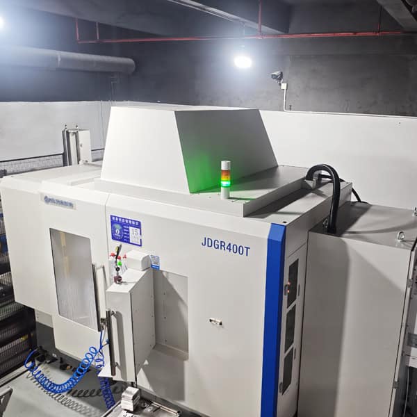
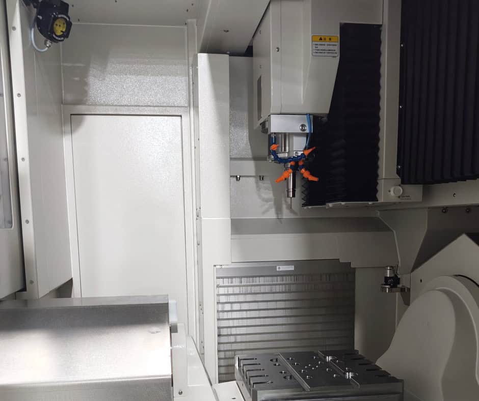
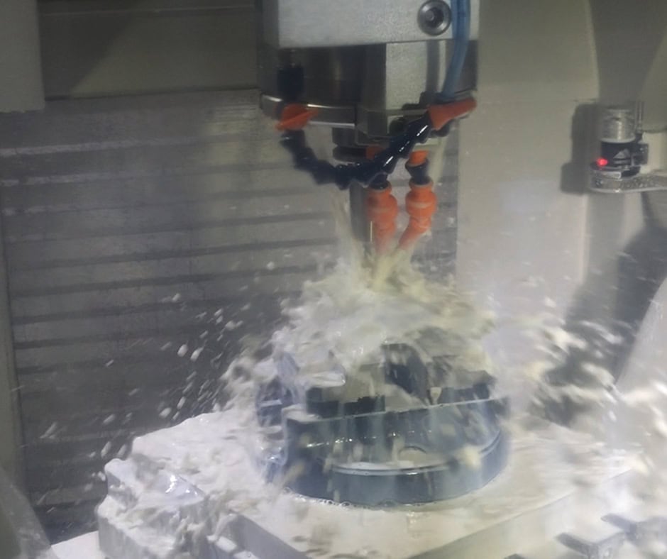
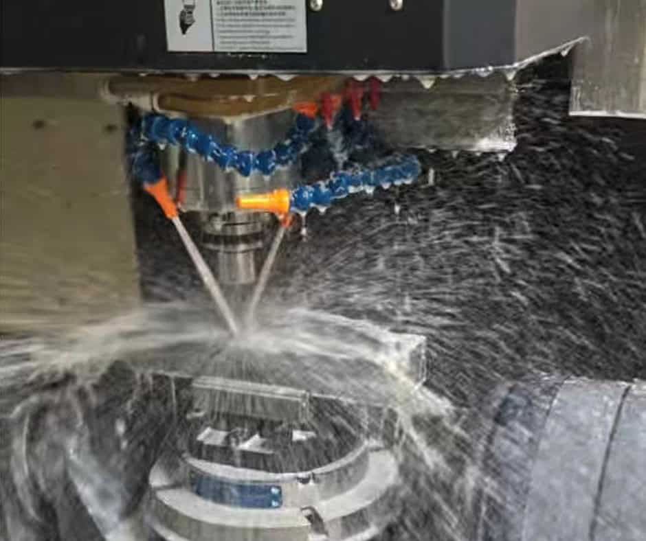
CNC machining is particularly important for the mechanical components of magnetic bearing spindles because many interfaces require controlled dimensional and geometric relationships.
CNC Turning
CNC turning is commonly used for spindle shafts, sleeves, cylindrical housings, spacers, and other rotational components.
Critical shaft features may include bearing locations, shoulders, threads, grooves, and tool or coupling interfaces.
The machining sequence should be planned to maintain the relationship between these features and the primary rotational axis.
CNC Milling
Milling is useful for producing spindle housings, mounting structures, cooling features, sensor pockets, cable passages, and other non-rotational geometry.
Depending on the housing configuration, multiple machining orientations may be required.
Drilling, Tapping, and Reaming
Precision holes may be required for bearings, sensors, fasteners, locating pins, cooling passages, or assembly interfaces.
Reaming or precision boring can be considered where a standard drilled hole does not provide sufficient dimensional control.
Multi-Axis Machining
Complex spindle housings may benefit from four- or five-axis machining when several surfaces or features need to be manufactured in controlled spatial relationships.
The value of multi-axis machining is primarily determined by the geometry and datum structure rather than the number of machine axes alone.
Key CNC Machining Challenges
1. Maintaining Concentricity of Rotating Features
One of the most important challenges is keeping multiple cylindrical features aligned with the spindle axis.
Bearing seats, rotor interfaces, shoulders, and other functional surfaces may need to share a controlled axis.
A suitable datum strategy, stable workholding, and appropriate machining sequence are essential.
2. Controlling Shaft Runout
A shaft can meet its individual diameter dimensions while still having unacceptable runout relative to another functional feature.
Therefore, inspection must evaluate the relevant geometric relationship rather than checking diameters independently.
Precision turning, suitable workholding, controlled finishing, and appropriate measurement methods help address this issue.
3. Machining Thin-Wall Housings
Magnetic bearing spindle housings may contain cavities, pockets, sensor areas, and cooling structures that leave relatively thin walls.
Machining forces and clamping pressure can distort these structures.
Staged material removal, optimized fixturing, and finishing passes can help maintain the final geometry.
4. Sensor and Magnetic Component Interfaces
Sensor mounting locations and magnetic bearing structures can be sensitive to dimensional variation.
A small positional difference can change the relationship between the sensor and rotor or affect the intended electromagnetic geometry.
These features should therefore be machined from controlled datums and inspected according to their functional requirements.
5. Surface Cleanliness
Magnetic bearing spindles may contain sensitive internal components and small operating clearances.
Machining chips, burrs, coolant residue, or other contaminants can interfere with assembly.
Deburring and cleaning should therefore be treated as controlled manufacturing steps rather than cosmetic finishing.
Quality Control
Magnetic bearing spindles generally require quality control at both the component and assembly levels.
Mechanical components should be manufactured according to customer drawings, CAD models, specifications, and functional requirements rather than relying on a generic tolerance standard.
Typical inspection items can include:
Shaft diameters
Bearing seat dimensions
Concentricity
Runout
Cylindricity
Flatness
Parallelism
Perpendicularity
Hole position
Thread dimensions
Surface finish
Housing dimensions
Rotor-to-housing interfaces
Depending on the design, inspection may use micrometers, bore gauges, height gauges, roundness or form measurement equipment, optical measurement systems, and CMM equipment.
For critical rotating components, dimensional inspection alone may not be sufficient. Rotor balancing and functional testing may also be required according to the complete spindle specification.
Inspection requirements should be established before production so that manufacturing, measurement, and acceptance criteria are aligned.
Applications
Magnetic bearing spindles are used where the advantages of contact-free rotor support justify their additional system complexity.
1. High-Speed Machine Tools
High-speed machining systems can benefit from spindle architectures designed to minimize mechanical bearing limitations.
Low friction and controlled rotor support can be valuable where rotational speed and dynamic performance are major design priorities.
2. Semiconductor and Electronics Manufacturing
Manufacturing equipment for semiconductor and electronic components may require clean, stable, high-speed motion.
The absence of conventional bearing lubrication at the active magnetic interface can be advantageous where contamination control is important.
3. Turbo Machinery
Magnetic bearing technology can be applied to certain compressors, expanders, turbines, and other high-speed rotating equipment.
The ability to support a rotor without conventional continuous bearing contact can be useful for selected high-speed applications.
4. Vacuum Equipment
Vacuum environments can place restrictions on conventional lubricants and mechanical bearing systems.
Magnetic bearing spindles can provide an alternative architecture where minimizing lubrication-related contamination is important.
5. Precision Measurement and Test Equipment
High-speed measurement systems may require controlled rotation with low mechanical disturbance.
Magnetic bearing systems can be considered when low vibration and controlled rotor positioning are important to measurement performance.
6. Advanced Manufacturing Equipment
Specialized laser processing, coating, inspection, and other precision manufacturing systems may incorporate high-speed spindle technology where conventional bearings are not optimal for the required operating conditions.
Magnetic Bearing Spindles vs. Air Bearing Spindles
An air bearing spindle is a closely related alternative that also supports a rotor without conventional rolling contact, but it uses a thin film of pressurized air rather than electromagnetic force.
| Factor | Magnetic Bearing Spindles | Air Bearing Spindles |
| Support principle | Electromagnetic force | Pressurized air film |
| Mechanical contact | No contact during normal magnetic operation | No contact during normal air-film operation |
| Control | Requires sensors and feedback control | Requires air supply and pressure control |
| Cleanliness | No bearing lubricant at active magnetic interface | No conventional bearing lubricant |
| Infrastructure | Electrical control and power electronics | Compressed/clean air infrastructure |
| Load characteristics | Highly design-dependent and actively controllable | Strongly dependent on air-film design and pressure |
| Manufacturing | Tight rotor, housing, and magnetic interfaces | Tight bearing surfaces and air gaps |
| Typical consideration | High-speed systems requiring active rotor control | Precision applications suited to air-film support |
Choose magnetic bearing spindles when active electronic control of rotor position, high-speed operation, and reduced mechanical contact are important and the system can accommodate the required control architecture.
An air bearing spindle may be preferable when the application already has a suitable clean compressed-air supply and the air-film bearing characteristics match the required load, speed, and stiffness.
Neither technology is universally superior. The appropriate solution depends on the operating environment, speed, load, vibration requirements, available infrastructure, and overall system architecture.
Cost and Procurement Considerations
Magnetic bearing spindles can involve higher development and integration costs than conventional spindle architectures because the system includes mechanical, electromagnetic, sensing, control, and cooling elements.
Material
Rotor and housing material selection affects raw-material cost, machinability, weight, thermal behavior, and magnetic performance.
Geometry
Complex housings, multiple precision bores, sensor pockets, cooling channels, and specialized interfaces increase machining requirements.
Tolerance
Critical rotor and housing interfaces may require tighter dimensional and geometric control.
Tolerances should be specified according to actual function. Unnecessarily tight tolerances can increase cost without improving spindle performance.
Machining Time
Complex multi-axis machining, precision turning, additional finishing operations, and specialized workholding can increase cycle time.
Surface Treatment
Surface treatments may be required for corrosion resistance, wear resistance, or specific environmental conditions. Compatibility with the magnetic and mechanical design should be evaluated first.
Inspection and Testing
Inspection requirements can include dimensional reports, CMM measurement, geometric verification, rotor balance, surface inspection, or functional testing depending on the project.
Prototype / Low-Volume / OEM / Production
Prototype: Useful for validating mechanical interfaces, rotor geometry, sensor positioning, and assembly concepts.
Low-volume: Suitable for specialized machinery, development programs, and pilot equipment.
OEM: Requires controlled engineering revisions, repeatable materials and processes, traceable inspection, and stable supplier performance.
Production: Requires process optimization, dedicated fixtures where appropriate, controlled inspection procedures, and repeatable machining conditions.
Customization and Quotation
Custom mechanical components for magnetic bearing spindles can be manufactured around the specific requirements of a spindle system.
Possible customization includes:
Shaft diameter and length
Bearing interfaces
Rotor geometry
Housing dimensions
Mounting interfaces
Sensor mounting features
Cooling passages
Threaded holes
Locating features
Surface finish
Surface treatment
Material
Inspection requirements
For an accurate quotation, buyers should ideally provide:
2D engineering drawing
3D CAD file
Material specification
Quantity
Critical tolerances
Surface finish requirements
Surface treatment
Inspection requirements
For high-speed rotating components, it is also useful to identify functional requirements such as operating speed, load conditions, balance requirements, or critical interfaces when these are already defined by the engineering team.
A complete drawing allows the manufacturer to distinguish critical dimensions from non-critical features and select an appropriate machining and inspection strategy.
Frequently Asked Questions
1. What are magnetic bearing spindles used for?
Magnetic bearing spindles are used for high-speed rotating applications where reduced mechanical contact, low wear, controlled rotor positioning, cleanliness, or dynamic performance is important.
2. What materials are used for magnetic bearing spindle components?
Depending on the design, shafts and structural components may use steels or other engineered alloys, while housings may use aluminum or steel. Specialized magnetic and electrical materials may also be required for the electromagnetic system.
3. Can magnetic bearing spindle components be CNC machined?
Yes. CNC turning, milling, drilling, boring, reaming, and multi-axis machining can be used for many spindle shafts, housings, mounting components, and precision interfaces.
4. What makes machining magnetic bearing spindles difficult?
The most demanding areas often include concentricity between rotating features, shaft runout, precision housing geometry, sensor locations, thin-wall structures, and controlled surface cleanliness.
5. Do magnetic bearing spindles require conventional bearings?
Many magnetic bearing systems incorporate auxiliary or backup bearings to support the rotor during abnormal conditions, startup, shutdown, or loss of magnetic support. The exact configuration depends on the spindle design.
6. What information is needed to quote a custom magnetic bearing spindle component?
A 2D drawing and 3D CAD model are the preferred starting points. Material, quantity, critical tolerances, surface finish, surface treatment, inspection requirements, and relevant operating conditions should also be provided when available.
Conclusion
Magnetic bearing spindles combine precision mechanical engineering with electromagnetic control to support high-speed rotation without relying on conventional continuous bearing contact at the primary support locations.
Their value is most apparent in applications where high rotational speed, low wear, cleanliness, vibration control, or controlled rotor positioning is important. At the same time, the technology introduces additional requirements for sensors, control electronics, thermal management, auxiliary bearings, and precision mechanical interfaces.
From a manufacturing perspective, the most important challenges are often not individual dimensions but the relationships between them. Shaft concentricity, runout, bearing interfaces, housing geometry, sensor locations, and rotor clearances must be controlled relative to the correct engineering datums.
CNC turning, milling, boring, reaming, and multi-axis machining can provide the mechanical precision required for these components, while appropriate inspection and, where required, balancing and functional testing complete the quality-control process.
For procurement teams, the best results come from defining the operating requirements before selecting a manufacturing approach. A complete drawing, CAD model, material specification, quantity, critical tolerances, finishing requirements, and inspection criteria allow the supplier to develop a process that matches the actual spindle design.
Ultimately, magnetic bearing spindle manufacturing is not simply about achieving tight dimensions. It is about creating a stable relationship between the rotor, bearing system, housing, motor, sensors, and control system, so that the complete spindle can perform reliably at its intended operating conditions.