1. Product Overview
A Scanner Mounting Bracket is a mechanical support component designed to secure, position, and align a scanner or scanning module within a larger equipment assembly. Depending on the application, the scanner may be an optical scanner, laser scanner, barcode scanner, imaging sensor, 3D scanner, document-scanning mechanism, or another precision sensing device.
Unlike a simple structural support, a scanner mounting bracket can directly influence the positional relationship between the scanner and its target. Small changes in mounting position, angular alignment, or mechanical stability can affect the scanner’s field of view, sensing range, image quality, or measurement repeatability.
The bracket therefore serves several engineering purposes:
Secures the scanner to the equipment frame
Establishes a repeatable mounting position
Maintains the required orientation of the scanning device
Controls the relationship between the scanner and the target surface
Provides mounting interfaces for screws, locating features, or adjustment mechanisms
Helps isolate or manage mechanical vibration
Integrates the scanner into a compact equipment structure
A typical scanner mounting bracket may include a base plate, vertical support, mounting flange, threaded holes, locating holes, slots, pockets, bosses, or other machined features. The exact configuration depends heavily on the scanner housing and the surrounding equipment.
For example, a compact scanner may use a relatively small aluminum bracket with several precision mounting holes. A larger industrial scanning system may require a reinforced structure with multiple mounting surfaces and additional adjustment features.
Common materials include aluminum alloys, stainless steel, carbon steel, and engineering plastics. Aluminum is often useful when weight, machinability, and corrosion resistance need to be balanced. Stainless steel can be selected when greater environmental resistance or structural durability is required. Engineering plastics may be appropriate for lightweight or electrically isolated applications, depending on the scanner’s operating environment.
For OEM equipment, a custom CNC machined scanner mounting bracket is often developed from the customer’s 2D drawing and 3D CAD model so that the mounting geometry corresponds directly with the scanner and machine assembly.
Table of Contents
2. Design and Performance
The engineering requirements of a scanner mounting bracket depend on the type of scanner and the accuracy expected from the complete system. Six characteristics are particularly important.
2.1 Positioning Accuracy
The primary function of the bracket is to establish the scanner’s position.
The critical dimensions may include:
Distance from the mounting datum to the scanner interface
Hole-to-hole spacing
Scanner centerline location
Mounting height
Angular orientation
Distance between the scanner and target
Even when the scanner itself has sophisticated electronic calibration, mechanical positioning still matters. If the bracket allows excessive movement or dimensional variation, the scanner’s relationship to the target can change.
For this reason, tolerances should be applied according to the functional requirements of the equipment rather than making every dimension unnecessarily tight.
2.2 Rigidity
A scanner mounting bracket should remain stable during operation.
Insufficient stiffness can result in small changes in scanner position caused by vibration, cable forces, acceleration, or mechanical loads. In measurement and imaging applications, such movement may translate into inconsistent results.
Bracket rigidity depends on:
Material
Wall thickness
Support geometry
Cantilever length
Mounting-point arrangement
Reinforcing ribs
Fastener configuration
A well-designed bracket often achieves stiffness through geometry rather than simply increasing material thickness.
2.3 Vibration Resistance
Industrial scanners may be installed on machinery containing motors, conveyors, actuators, or other vibration sources.
The bracket should therefore maintain its position under the expected operating environment.
Potential problems caused by vibration include:
Fastener loosening
Scanner movement
Image or measurement instability
Mechanical fatigue
Noise
Progressive loss of alignment
Depending on the equipment, vibration isolation may be incorporated between the scanner and bracket, or between the bracket and the main machine frame.
The bracket design should be considered together with the complete mounting system rather than treated as an isolated component.
2.4 Thermal Stability
Temperature changes can affect dimensional relationships within precision equipment.
This is particularly relevant when the scanner is installed near heat-generating electronics, motors, lasers, or lighting systems.
Material selection, bracket geometry, and mounting configuration can influence thermal behavior. Aluminum, for example, offers good thermal conductivity but has a relatively high coefficient of thermal expansion compared with many steels.
When dimensional stability over a wide temperature range is important, the bracket should be evaluated together with the scanner housing and supporting structure.
2.5 Surface and Interface Quality
The quality of the mounting interfaces can influence assembly repeatability.
Critical surfaces may require controlled:
Flatness
Parallelism
Perpendicularity
Surface roughness
Edge condition
A mounting surface that is uneven or contaminated by burrs can prevent the scanner from seating consistently.
2.6 Long-Term Reliability
A scanner mounting bracket is often expected to remain installed for long periods. Reliability therefore involves more than initial dimensional accuracy.
The design should account for:
Repeated installation and removal
Fastener loading
Environmental exposure
Vibration
Thermal cycling
Corrosion
Contact wear
For serviceable equipment, threaded holes and mounting surfaces should be designed for the expected maintenance cycle.
3. Materials and Design Options
Material selection should reflect the scanner’s weight, operating environment, required rigidity, thermal conditions, and manufacturing method.
| Material | Advantages | Considerations |
| Aluminum alloy | Lightweight, machinable, corrosion resistant | Lower stiffness than steel |
| Stainless steel | Strong, durable, corrosion resistant | Heavier and generally more difficult to machine |
| Carbon steel | High stiffness and economical | Usually needs protective surface treatment |
| Engineering plastic | Lightweight and electrically insulating | Mechanical and thermal capability depends on grade |
Aluminum Scanner Mounting Brackets
Aluminum is a common choice for custom CNC machined scanner brackets because it provides a useful combination of low weight, machinability, and structural performance.
It can also be anodized or finished in other ways depending on the application.
For compact optical or electronic equipment, an aluminum bracket can reduce system weight while maintaining adequate rigidity when the geometry is properly designed.
Stainless Steel Designs
Stainless steel may be preferred when the bracket operates in humid, corrosive, or demanding industrial environments.
The additional weight may be acceptable when mechanical durability and environmental resistance are more important than lightweight construction.
Fixed vs. Adjustable Brackets
A fixed scanner mounting bracket provides a defined position and is appropriate when the scanner location is established during equipment design.
An adjustable scanner mounting bracket can incorporate slots, multiple mounting holes, sliding features, or adjustment screws. This can simplify calibration or allow one bracket design to accommodate multiple configurations.
However, adjustability can introduce additional mechanical interfaces and may reduce rigidity if the locking mechanism is not properly designed.
Lightweight vs. Reinforced Designs
A lightweight bracket may be appropriate for portable scanning equipment or compact electronics.
A reinforced design becomes more useful when the scanner is mounted on moving machinery, subjected to vibration, or positioned at a relatively long distance from the primary mounting plane.
The objective is not simply to maximize material. The bracket should achieve the required stiffness and stability without adding unnecessary mass or machining cost.
4. Manufacturing and CNC Machining
Scanner mounting brackets can be manufactured using several processes, including CNC machining, sheet metal fabrication, casting, injection molding, or combinations of these methods.
CNC machining is particularly useful for prototypes, low-volume production, and custom brackets requiring precise mounting interfaces.
CNC Milling
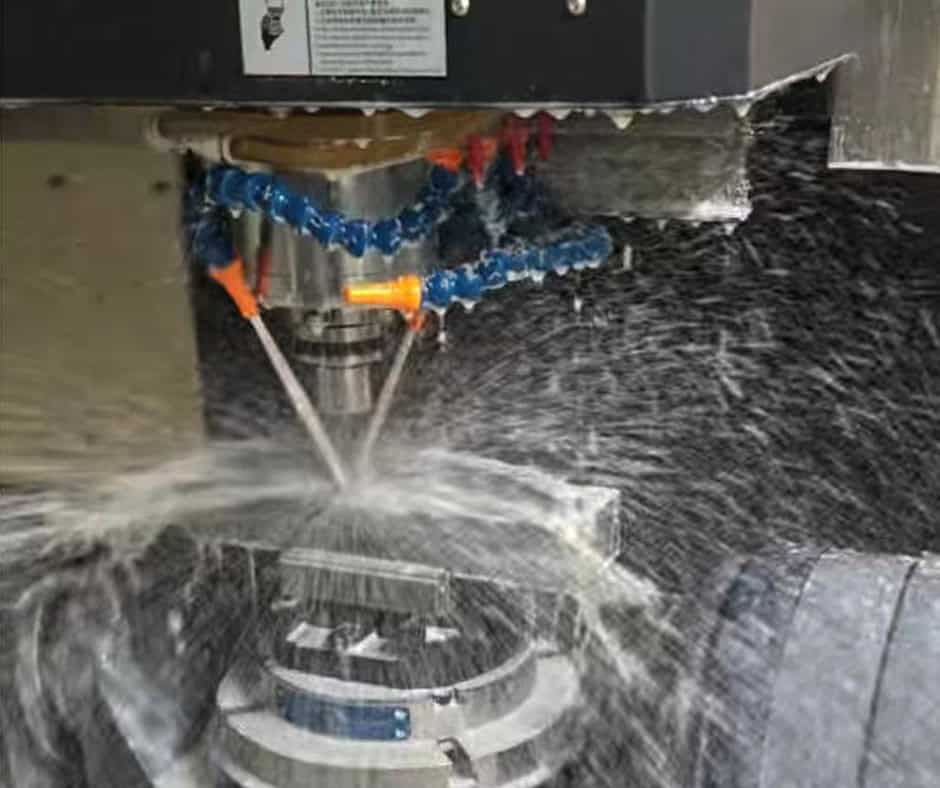
CNC milling can produce the majority of features found on a custom scanner bracket, including:
Mounting surfaces
Pockets
Counterbores
Threaded holes
Locating holes
Slots
Recesses
External contours
Lightweighting features
For more complex three-dimensional brackets, multi-axis machining can reduce the number of setups and improve access to difficult surfaces.
Drilling, Tapping, and Reaming
Mounting holes often have direct functional significance.
Drilled holes may be used for clearance fasteners, while tapped holes allow screws to be installed directly into the bracket.
Reaming may be appropriate when a locating hole requires tighter dimensional control than a conventional drilled hole can provide.
The choice of process should follow the function of the hole rather than applying the same tolerance to every opening.
Multi-Axis Machining
A three-axis CNC machine can manufacture many scanner brackets efficiently. More complex designs may benefit from four- or five-axis machining when multiple angled surfaces or difficult orientations are involved.
Multi-axis machining can reduce repositioning and improve consistency between related features, but it should be justified by part geometry and production requirements.
Deburring and Cleaning
Optical and electronic equipment can be sensitive to chips, burrs, and machining residue.
After machining, the bracket should therefore be properly deburred and cleaned. Particular attention should be given to threaded holes, pockets, small drilled holes, and internal corners where chips can remain trapped.
Surface Treatment
Depending on the material and operating environment, possible treatments include:
Anodizing
Powder coating
Plating
Passivation
Painting
Surface treatment should be specified together with functional dimensions because coating thickness can affect fits, threads, and mating surfaces.
5. Manufacturing Challenges
Scanner mounting brackets can contain several features that require careful process planning.
5.1 Controlling the Scanner Mounting Pattern
A scanner housing may have several mounting holes that must align with the bracket simultaneously.
If the hole pattern is machined incorrectly, assembly may require excessive force or become impossible.
Manufacturing approach: Establish a reliable datum system and machine related holes from controlled setups. Critical hole locations should be inspected relative to the appropriate datum features.
5.2 Maintaining Angular Relationships
Some scanners need to point at a specific angle relative to the equipment frame.
An angular mounting face or tilted interface can therefore be more critical than the external dimensions of the bracket.
Manufacturing approach: Use suitable workholding and machining strategies to establish the angular surface accurately, followed by inspection of the relevant geometric relationship.
5.3 Preventing Thin-Section Deformation
Lightweight brackets may contain thin walls or narrow support sections. Cutting forces can cause deflection during machining.
Manufacturing approach: Optimize workholding, tool engagement, machining sequence, and cutting conditions. Where necessary, the design can also incorporate ribs or thicker sections around load-bearing interfaces.
5.4 Protecting Precision Mating Surfaces
A mounting surface can be dimensionally correct but still perform poorly if it contains burrs or unwanted tool marks.
Manufacturing approach: Control the final machining operation, deburr carefully, and protect critical surfaces during subsequent handling and finishing.
5.5 Managing Multiple Datums
A scanner bracket may connect to both the scanner and the equipment frame. This means several surfaces and hole patterns may have positional relationships that need to be controlled together.
Manufacturing approach: Define the primary functional datums in the engineering drawing and develop the machining sequence around those references.
6. Quality Control
There is no universal dimensional specification for every scanner mounting bracket. Quality requirements should be established according to the customer’s engineering drawing and the functional requirements of the scanning system.
Important inspection characteristics may include:
Overall dimensions
Material
Mounting hole diameter
Hole position
Thread dimensions
Flatness
Parallelism
Perpendicularity
Angular features
Surface finish
Functional fit
For simple components, conventional calibrated inspection equipment may be sufficient.
For complex brackets containing multiple datum relationships, a coordinate measuring machine (CMM) may be used to verify the position of mounting holes, surfaces, and other critical features.
Functional inspection can also be useful. For example, a bracket may be checked against a mating scanner housing or assembly fixture to verify that the interfaces fit correctly.
The appropriate inspection level should reflect the actual risk of the application. A simple support bracket does not necessarily require the same inspection process as a bracket used to establish a critical optical measurement position.
7. Applications
7.1 Industrial Machine Vision
Scanner mounting brackets can position optical scanning devices within automated inspection equipment.
Precise positioning is important because the scanner must maintain a predictable relationship with the inspected component or conveyor.
7.2 Barcode and Identification Systems
Industrial barcode scanners are often installed above or beside conveyors.
Custom brackets allow the scanner to be positioned at the appropriate height and angle while keeping the mounting structure compact.
7.3 3D Scanning Equipment
3D scanners require controlled positioning relative to the object being measured.
A rigid custom bracket can help maintain scanner geometry and reduce unwanted movement during scanning.
7.4 Laser Scanning Systems
Laser scanners can be integrated into industrial automation, robotics, inspection systems, and sensing equipment.
Depending on the system, the bracket may need to provide a stable mounting angle and sufficient resistance to vibration.
7.5 Laboratory and Research Instruments
Scanning and imaging modules are used in laboratory equipment where space can be limited and mounting geometry may be highly customized.
CNC machining allows the bracket to be manufactured around the actual instrument architecture.
7.6 Automated Material Handling
Scanning modules used on conveyors, sorting systems, and automated logistics equipment may need robust brackets capable of maintaining alignment under continuous mechanical activity.
8. Scanner Mounting Bracket vs. Sensor Mounting Bracket
A Sensor Mounting Bracket is functionally similar to a scanner mounting bracket, but the two are not always interchangeable.
| Factor | Scanner Mounting Bracket | Sensor Mounting Bracket |
| Typical application | Optical or scanning devices | General sensors and detection devices |
| Positioning requirement | Often strongly related to scanning field or measurement geometry | Depends on sensor type |
| Design | May require precise orientation and larger mounting interfaces | Often compact and simpler |
| Adjustment | May require controlled angular or positional adjustment | Frequently fixed, depending on application |
| Manufacturing | CNC machining or fabricated structures | CNC, sheet metal, molded, or standard brackets |
| Cost | Highly dependent on alignment requirements | Usually dependent on size and complexity |
Choose a Scanner Mounting Bracket when the mounting component must establish a defined relationship between a scanner and its scanning target.
A more general Sensor Mounting Bracket may be preferable when the device is a proximity sensor, temperature sensor, photoelectric sensor, or another sensor whose mounting requirements are less dependent on a specific scanning geometry.
The distinction ultimately comes from the equipment’s functional requirements rather than the name of the bracket.
9. Cost and Procurement Considerations
The cost of a custom scanner mounting bracket is influenced by several interconnected factors.
Material
Material cost varies significantly between aluminum, stainless steel, carbon steel, and engineering plastics.
Material choice should be based on actual mechanical and environmental requirements rather than simply selecting the lowest material price.
Geometric Complexity
A simple plate with several holes requires less machining than a bracket containing pockets, angled surfaces, ribs, and multiple mounting planes.
Complex geometry generally increases programming, setup, tooling, and machining time.
Tolerances
Tighter tolerances can increase inspection and production requirements. Buyers should identify critical dimensions clearly rather than applying tight tolerances indiscriminately.
Quantity
Prototype and production quantities have different cost structures.
For a single prototype, programming and setup costs can represent a significant portion of the total price. In production, these costs can be distributed over a larger quantity.
Machining Time
Material removal volume, number of machining operations, workholding requirements, and tool changes all affect the manufacturing cycle.
Surface Treatment
Anodizing, plating, powder coating, and other treatments add additional processing costs.
Inspection
Basic dimensional inspection may be sufficient for a straightforward bracket. More demanding applications may require CMM inspection, inspection reports, material documentation, or other quality requirements.
10. Prototype, Low-Volume, OEM, and Production
Prototype
CNC machining is well suited to scanner bracket prototypes because engineers can quickly evaluate the physical fit, scanner position, cable clearance, and assembly process before committing to larger production quantities.
Low-Volume Production
For small quantities, CNC machining can avoid the tooling investment associated with certain mass-production processes.
This makes it useful for specialized equipment and engineering systems with relatively low annual demand.
OEM Production
OEM buyers typically require consistent dimensions and repeatable manufacturing across production batches.
The engineering drawing should clearly define critical features, material, finishing, tolerances, and inspection requirements.
Production Volume
When annual demand becomes high, alternative processes such as stamping, die casting, extrusion, or injection molding may become more competitive depending on the bracket’s geometry and material.
The best process should therefore be evaluated based on total production economics rather than the unit machining cost alone.
11. Customization and Quotation
A custom Scanner Mounting Bracket can be designed around the scanner housing and the equipment’s actual mounting environment.
Common customization options include:
Overall length, width, and height
Material and material thickness
Scanner mounting hole pattern
Thread size and type
Locating holes
Slots and adjustment features
Mounting angles
Pockets and weight-reduction features
Reinforcement ribs
Surface finish
Surface treatment
Identification markings
For quotation, buyers should ideally provide:
2D engineering drawing
3D CAD file
Material specification
Quantity
Required tolerances
Surface finish
Surface treatment
Inspection requirements
Special assembly requirements
A 3D CAD model provides the overall geometry, while a 2D drawing is normally important for defining manufacturing requirements such as tolerances, threads, surface finishes, and material specifications.
If the scanner bracket is part of a larger assembly, providing information about the mating components or critical interfaces can also help the manufacturer evaluate manufacturability.
12. FAQs
What is a Scanner Mounting Bracket?
A Scanner Mounting Bracket is a mechanical component used to secure and position a scanner or scanning module within equipment. It establishes the required mechanical relationship between the scanner, equipment structure, and scanning target.
Can Scanner Mounting Brackets be CNC machined?
Yes. CNC milling is particularly suitable for custom scanner brackets containing precise mounting holes, threaded features, pockets, locating surfaces, and complex profiles.
What material is commonly used for scanner brackets?
Aluminum is often suitable for lightweight equipment because it combines relatively low weight with good machinability. Stainless steel or carbon steel may be selected when greater rigidity, durability, or environmental resistance is required. The appropriate material depends on the application.
Does a scanner bracket need tight tolerances?
Not every dimension needs a tight tolerance. Critical features such as scanner mounting holes, locating surfaces, and angular interfaces may require tighter control depending on the equipment design. Requirements should be specified according to the engineering drawing.
Can the mounting bracket be adjustable?
Yes. Slots, multiple hole positions, sliding features, or other adjustment mechanisms can be incorporated when the scanner needs calibration or positional flexibility. However, the design must maintain adequate rigidity after adjustment.
What files are needed for a quotation?
A 2D drawing and 3D CAD model are normally the most useful documents. Material, quantity, tolerances, surface finish, surface treatment, and inspection requirements should also be provided when applicable.
13. Conclusion
A Scanner Mounting Bracket is more than a simple mechanical support. In optical, imaging, scanning, and automated inspection equipment, it can establish the physical relationship that allows a scanner to operate consistently relative to its target.
Effective bracket design therefore begins with the functional requirements of the complete system. Positioning accuracy, rigidity, vibration resistance, thermal behavior, interface quality, and long-term reliability should be considered together.
Material selection also needs to reflect the operating environment. Aluminum can provide an effective balance between weight and machinability, while stainless steel or reinforced designs may be more appropriate for demanding industrial conditions.
From a manufacturing perspective, CNC machining provides flexibility for custom geometries and precision mounting features, particularly for prototypes, low-volume production, and specialized OEM equipment. Careful control of datums, hole positions, angular surfaces, thin sections, burrs, and mating interfaces is essential for producing a bracket that fits the intended assembly.
For procurement teams, the most reliable approach is to provide complete engineering information and distinguish critical functional tolerances from non-critical dimensions. When design requirements, material, manufacturing process, finishing, and inspection are aligned from the beginning, a custom scanner mounting bracket can provide a stable and repeatable mechanical interface throughout the equipment’s service life.