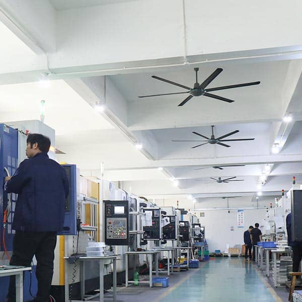
Product Overview
A light emitting mirror pressing plate is a precision mechanical component used to retain, position, or apply controlled pressure to a mirror, optical element, or related component within an optical assembly. Although its structure may appear relatively simple, the plate can have a direct influence on optical alignment, component stability, assembly repeatability, and long-term reliability.
The exact configuration depends on the equipment in which the pressing plate is installed. A typical design may include a flat or contoured plate body, mounting holes, threaded holes, locating features, clearance areas, and a contact surface that interfaces with the mirror or an intermediate retaining element.
The main engineering purpose is not simply to “hold a mirror.” The plate must secure the optical component without introducing excessive mechanical stress or unwanted movement. In applications involving emitted or reflected light, even small changes in component position or orientation can affect the optical path.
Typical functions include:
Securing a mirror or optical component inside an assembly
Maintaining a defined position during operation
Distributing clamping force over a controlled area
Preventing movement caused by vibration or equipment handling
Supporting repeatable assembly and maintenance
Providing mechanical integration between the optical component and its housing
Common materials include aluminum alloys, stainless steel, and engineering steels. Aluminum is often selected when low weight and good machinability are important. Stainless steel can be preferable where corrosion resistance, rigidity, or dimensional stability is more important. The final material should be selected according to the mechanical load, environment, thermal conditions, weight requirements, and drawing specifications.
Because optical assemblies can be sensitive to mechanical deformation, the pressing plate should be treated as a functional component rather than a generic metal plate.
Table of Contents
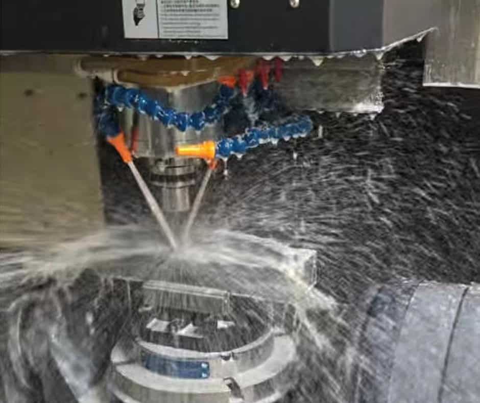
Design and Performance Considerations
The performance of a light emitting mirror pressing plate depends on the relationship between its geometry, material, mounting method, and contact with the optical component. Several engineering characteristics are particularly important.
1. Dimensional Accuracy
The overall dimensions determine whether the pressing plate fits correctly into the optical assembly. Hole positions, mounting patterns, thickness, locating features, and contact geometry may all affect assembly.
Accuracy becomes especially important when the plate works together with other precision-machined components. A small dimensional deviation can create assembly interference or change the position of the retained component.
For custom parts, critical dimensions should therefore be identified on the engineering drawing rather than assuming that every dimension requires the same tolerance.
2. Flatness and Contact Stability
A pressing plate normally needs a controlled contact surface. Excessive surface variation can cause uneven loading, poor seating, or localized pressure.
Flatness is particularly relevant when the plate contacts an optical component directly or works against a precision reference surface. The required flatness should be established according to the assembly design.
A practical design may also use pads, retaining inserts, flexible elements, or other interfaces to control how force is transferred to the optical component.
3. Positioning and Hole Location
Mounting and locating holes determine how accurately the pressing plate can be installed.
Critical hole locations may need tighter positional control than non-functional features. This is especially important when several components share a common mounting pattern.
Depending on the design, CNC milling followed by precision drilling, reaming, or thread machining can provide the required positional relationship.
4. Controlled Clamping Force
A pressing plate must retain the mirror without unnecessarily loading it.
If the plate is too flexible, the component may move during vibration or thermal cycling. If the structure is excessively rigid or the fastening system produces too much force, the optical element may experience unwanted stress.
The solution is normally a combination of:
Appropriate plate thickness
Suitable contact geometry
Correct fastener arrangement
Controlled contact area
Appropriate material selection
Proper assembly procedure
The pressing plate itself does not determine clamping force independently; the entire retention system must be considered.
5. Thermal Stability
Optical equipment can experience temperature changes during operation, transportation, or environmental exposure.
Different materials expand at different rates. If the pressing plate and surrounding components have significantly different thermal expansion characteristics, temperature changes can influence contact pressure or component position.
For this reason, material selection should consider not only strength and machining cost but also the thermal environment and the materials of mating components.
6. Vibration Resistance
Laser equipment, optical instruments, industrial inspection systems, and other machinery may experience vibration.
The plate must maintain its position under normal operating conditions. Threaded fasteners, locating features, plate thickness, and mounting geometry all influence vibration resistance.
A rigid structure alone is not necessarily sufficient. The complete assembly needs an appropriate fastening and retention strategy.
7. Surface Quality and Cleanliness
Optical assemblies often require cleaner manufacturing conditions than ordinary mechanical components.
Sharp burrs, loose particles, machining residue, or excessive surface roughness can interfere with assembly or contaminate nearby optical components.
Consequently, deburring, cleaning, and inspection can be important parts of production even when the component itself does not directly interact with the optical beam.
Materials and Design Options
Material selection should be based on the actual operating requirements rather than simply choosing the lowest-cost material.
| Material | Advantages | Typical Considerations |
| Aluminum alloys | Lightweight, highly machinable, good strength-to-weight ratio | Lower stiffness than many steels; surface treatment may be required |
| Stainless steel | Corrosion resistance, rigidity, durability | Heavier and generally slower to machine |
| Carbon/alloy steel | High rigidity and strength | May require protective surface treatment |
| Engineering plastics | Low weight and electrical insulation in selected applications | Thermal stability and stiffness must be evaluated carefully |
Fixed vs. Adjustable Designs
A fixed pressing plate is appropriate when the optical component has already been precisely positioned by the surrounding structure. It is generally simpler to manufacture and assemble.
An adjustable design may incorporate slots, adjustment screws, or other mechanisms when the retained component requires positional adjustment.
The adjustable approach can provide greater flexibility but introduces additional components, manufacturing requirements, and potential sources of movement.
Standard vs. Custom Designs
Standard retaining components may be suitable for simple optical assemblies with established dimensions.
Custom pressing plates are more appropriate when the mirror size, mounting pattern, available space, or optical alignment requirements are specific to the equipment.
For OEM equipment, the pressing plate is often designed together with the housing and other optical mounting components rather than selected as an independent catalog part.
Lightweight vs. Reinforced Construction
A lightweight plate can reduce system mass, which may be useful in compact optical equipment or moving assemblies.
A reinforced plate may be preferable when stiffness and vibration resistance are more important.
Features such as ribs, thicker sections, optimized mounting locations, and localized reinforcement can increase rigidity without necessarily making the entire component unnecessarily thick.
Manufacturing and CNC Machining
A light emitting mirror pressing plate is commonly manufactured through CNC machining when its geometry, hole pattern, or tolerances require controlled production.
CNC Milling
CNC milling is suitable for producing:
Plate profiles
Recesses and pockets
Mounting surfaces
Locating features
Slots
Counterbores and countersinks
Complex three-dimensional contours
For relatively simple plates, three-axis milling may be sufficient. More complex geometries may benefit from four- or five-axis machining depending on the drawing.
Drilling, Tapping, and Reaming
Threaded mounting holes can be produced by CNC tapping, while precision holes may require drilling followed by reaming.
Hole-making strategy should be selected according to the required diameter, tolerance, depth, thread specification, and positional relationship.
Multi-Axis Machining
Multi-axis machining can be useful when the pressing plate contains angled surfaces, complex pockets, or multiple machining orientations.
The main benefit is not simply a higher machine-axis count. Proper fixturing and datum selection are often more important because they determine how accurately features from different operations relate to one another.
Key Machining Challenges
1. Maintaining Flatness After Machining
A relatively thin plate can deform during machining because of residual stress, clamping force, or uneven material removal.
A practical approach may involve staged machining, controlled clamping, appropriate tool paths, and finishing passes. For demanding components, the machining sequence should be developed around the final flatness requirement.
2. Maintaining Hole-to-Edge and Hole-to-Hole Relationships
The mounting pattern may be functionally more important than the nominal hole diameter.
If the plate connects multiple components, positional errors can accumulate during assembly. CNC programming should therefore establish the relevant datum structure from the engineering drawing and maintain the required feature relationships within the same coordinate system whenever practical.
3. Avoiding Burrs Around Precision Features
Burrs around holes, slots, or edges can interfere with assembly and may introduce unwanted particles into an optical system.
Controlled deburring should be included in the manufacturing process rather than treated as an informal final step.
4. Protecting Functional Surfaces
Clamping and machining can leave marks on visible or functional surfaces. This is particularly relevant if the pressing plate is installed next to sensitive optical components.
Fixtures should be designed to secure the workpiece while minimizing damage to critical surfaces.
5. Controlling Cleanliness
After machining, cutting fluid, chips, abrasive particles, and handling residue should be removed according to the cleanliness requirements of the final assembly.
The appropriate cleaning method depends on the material, surface treatment, and customer requirements.
Quality Control
There is no single universal dimensional specification that applies to every light emitting mirror pressing plate. These components are normally manufactured according to the customer’s drawing, CAD model, specifications, and functional requirements.
Typical inspection items include:
Overall dimensions
Thickness
Flatness
Parallelism
Perpendicularity
Hole diameter
Hole position
Thread dimensions
Pocket dimensions
Surface finish
Edge and burr condition
Functional fit with mating components
For relatively simple dimensions, calibrated gauges, micrometers, calipers, height gauges, and other conventional inspection equipment may be sufficient.
For complex geometry or critical positional relationships, a CMM may be used to verify the actual feature locations against the engineering definition.
Inspection requirements should be agreed before production, particularly when the customer requires inspection reports, dimensional records, or specific measurement methods.
Applications
Light emitting mirror pressing plates can be used in various optical and photonic systems where a mirror or related optical component requires controlled mechanical retention.
1. Laser Equipment
Laser systems may contain mirrors used to guide or redirect an optical beam.
The pressing plate helps secure the mirror while maintaining the mechanical relationship between the optical component and its mounting structure.
2. Optical Inspection Equipment
Machine-vision and optical inspection systems can contain multiple optical components whose relative positions influence imaging performance.
A custom pressing plate can provide a repeatable mechanical interface within the optical module.
3. Photonic and Fiber-Optic Equipment
Some photonic assemblies use precision optical elements in compact mechanical structures.
The pressing plate may help retain an optical component where space is limited and repeatable positioning is required.
4. Spectroscopy and Analytical Instruments
Analytical instruments can incorporate mirrors and optical elements as part of their light paths.
Material stability, dimensional accuracy, and cleanliness can become important because mechanical movement may influence optical alignment.
5. Optical Communication Equipment
Optical communication equipment may require compact precision components for optical routing or alignment.
Customized plates can integrate mounting, retention, and positioning functions into a small mechanical component.
Light Emitting Mirror Pressing Plate vs. Optical Lens Retaining Ring
A closely related alternative is an optical lens retaining ring. Both components can be used to secure optical elements, but their mechanical configurations are different.
| Factor | Light Emitting Mirror Pressing Plate | Optical Lens Retaining Ring |
| Application | Often used for mirrors or plate-like optical elements | Commonly used for round lenses and optical elements |
| Geometry | Plate-based, often rectangular or application-specific | Usually circular or threaded |
| Mounting | Screws, locating features, pockets, or clamps | Threads, shoulders, or retaining interfaces |
| Adjustment | Can incorporate slots or adjustable mounting features | Usually depends on the housing design |
| Manufacturing | CNC milling and hole machining are common | Turning and thread machining are often important |
| Design flexibility | High for OEM assemblies | High for cylindrical optical housings |
| Cost | Depends strongly on geometry and machining time | Often economical for simple rotational designs |
The pressing plate is generally preferable when the optical component and surrounding assembly require a plate-based mounting solution, custom hole pattern, or integrated mechanical features.
A retaining ring may be a better choice when the optical component is circular and the housing is already designed around a threaded or shoulder-based retention system.
The correct choice should therefore be based on the optical component geometry and mechanical architecture rather than treating either component as a universal replacement.
Cost and Procurement Considerations
The price of a custom light emitting mirror pressing plate depends on several interacting factors.
Material
Aluminum is generally efficient to machine, while stainless steel and harder alloys may require more machining time and tooling consideration.
Geometry
A simple flat plate with drilled holes is significantly different from a plate containing multiple pockets, angled surfaces, fine features, or complex contours.
Tolerance
Tighter tolerances may require additional machining operations, better process control, and more extensive inspection.
Quantity
Prototype and low-volume orders typically have higher unit costs because programming, setup, fixturing, and inspection costs are distributed across fewer parts.
Higher production quantities can reduce the setup cost per part when the geometry and process remain stable.
Surface Treatment
Anodizing, plating, passivation, painting, or other treatments add processing and logistics costs.
The treatment should be selected according to the functional and environmental requirements rather than purely for appearance.
Inspection
Basic dimensional inspection is different from comprehensive dimensional verification using a CMM or documented inspection report.
Buyers should specify which characteristics are critical before requesting a quotation.
Prototype, Low-Volume, OEM, and Production
Prototype: Suitable for validating mechanical fit and optical assembly concepts.
Low-volume: Useful for engineering builds, pilot production, and specialized equipment.
OEM: Requires consistent drawings, revision control, quality requirements, and repeatable manufacturing.
Production: Process optimization, fixture design, inspection planning, and stable material sourcing become increasingly important.
Customization and Quotation
A custom light emitting mirror pressing plate can be manufactured around the customer’s specific mechanical and optical assembly.
Common customization options include:
Overall dimensions
Thickness
Mounting-hole pattern
Thread type and size
Counterbores and countersinks
Slots
Pockets
Locating features
Contact surfaces
Material
Surface finish
Surface treatment
Edge treatment
Inspection requirements
For an accurate quotation, buyers should normally provide as much of the following information as possible:
2D engineering drawing
3D CAD file
Material specification
Required quantity
Critical tolerances
Surface finish requirements
Surface treatment
Inspection requirements
Special packaging or cleanliness requirements, when applicable
A 3D model helps the manufacturer understand geometry, while a properly dimensioned 2D drawing normally provides the authoritative manufacturing requirements for dimensions, tolerances, threads, surface finish, and other specifications.
When no complete drawing is available, a manufacturer may still be able to review a CAD model and discuss the missing engineering information before quoting.
Frequently Asked Questions
1. What is a light emitting mirror pressing plate used for?
A light emitting mirror pressing plate is primarily used to mechanically retain and position a mirror or related optical component within an optical or photonic assembly. Its exact function depends on the equipment design.
2. What material is best for a light emitting mirror pressing plate?
There is no universally best material. Aluminum is often considered when low weight and machinability are important, while stainless steel or steel may be selected when greater rigidity, durability, or environmental resistance is required. The final choice should follow the application and engineering drawing.
3. Can the pressing plate be customized?
Yes. Customization can include dimensions, hole patterns, threads, pockets, locating features, material, surface treatment, and other geometry specified by the customer.
4. How accurately can a light emitting mirror pressing plate be CNC machined?
The achievable accuracy depends on the material, geometry, size, tolerance requirements, machining process, and inspection method. Critical dimensions should be specified on the drawing rather than relying on a generic machining tolerance.
5. Should the pressing plate be anodized or otherwise surface treated?
That depends on the material and application. Surface treatment may improve corrosion resistance, wear resistance, appearance, or surface properties, but compatibility with the optical assembly should be considered before selecting a treatment.
6. What information is needed to quote a custom part?
A 2D drawing and 3D CAD file are the most useful starting points. Material, quantity, critical tolerances, surface finish, surface treatment, and inspection requirements should also be provided when applicable.
Conclusion
A light emitting mirror pressing plate is a small mechanical component with an important role in maintaining the position and stability of optical elements. Its engineering value comes from the way the plate integrates with the surrounding optical and mechanical structure.
Successful design requires more than selecting a piece of metal and adding mounting holes. Flatness, dimensional relationships, clamping behavior, thermal conditions, vibration, surface quality, and cleanliness can all influence the final assembly.
From manufacturing perspective, CNC milling, precision hole machining, controlled fixturing, deburring, cleaning, surface treatment, and dimensional inspection may all contribute to a reliable result. The appropriate process depends on the geometry and requirements defined by the customer.
For buyers, the most effective approach is to provide a clear drawing and CAD model together with material, quantity, tolerance, finishing, and inspection requirements. This allows the manufacturer to evaluate machining complexity accurately and recommend a production process suited to the actual application.
Ultimately, the right light emitting mirror pressing plate is not necessarily the one with the most complicated design. It is the one whose material, geometry, manufacturing process, and inspection requirements are properly matched to the optical assembly it supports.