Product Overview
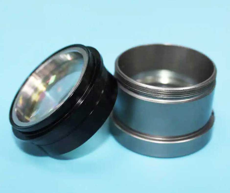
A Fiber Optic Adjustable Mirror Tube is a precision mechanical component used to support, position, and align optical elements such as mirrors, lenses, fiber-optic interfaces, or other photonic components. Its primary purpose is not simply to hold an optical element in place, but to provide a controlled mechanical interface that helps maintain the required optical path and alignment.
In fiber-optic and laser-based equipment, even a relatively small positional error can affect coupling efficiency, beam direction, focal position, or system repeatability. For this reason, the mechanical structure surrounding an optical component can be just as important as the optical component itself.
An adjustable mirror tube typically combines a cylindrical or tubular body with mounting features and an adjustment mechanism. Depending on the design, the assembly may include:
A cylindrical main tube or housing
An internal or external mounting interface
A mirror or optical-element seat
Threaded adjustment features
Locking screws or retaining elements
Mounting holes or flange features
Precision-machined locating surfaces
The exact configuration depends on the optical system and the customer’s mechanical interface requirements.
Unlike a generic tube, an adjustable mirror tube usually requires controlled relationships between several features. For example, the axis of a threaded bore, the optical mounting surface, and the external mounting reference may need to remain accurately positioned relative to one another.
Common Materials
Aluminum alloys are frequently considered when low weight, machinability, and adequate structural rigidity are important. Stainless steel may be selected when higher stiffness, wear resistance, corrosion resistance, or dimensional stability is required.
Other engineering materials can be used depending on the application, including brass or specific engineering plastics. Material selection should consider not only machining cost but also thermal expansion, environmental conditions, weight, surface treatment, and interaction with adjacent optical components.
Table of Contents
Design and Performance Considerations
The performance of a Fiber Optic Adjustable Mirror Tube depends on the relationship between its geometry, adjustment mechanism, material, and manufacturing accuracy. Several engineering characteristics deserve particular attention.
1. Dimensional Accuracy
The tube may contain multiple coaxial, threaded, bored, and mounting features. Their relative positions can influence how accurately the optical component is positioned.
Dimensional accuracy is particularly important when the tube interfaces with other precision components. A bore that is dimensionally correct but poorly aligned with the external mounting reference can still create problems during assembly.
Critical dimensions should therefore be defined according to the optical system’s functional requirements rather than applying unnecessarily tight tolerances to every feature.
2. Positioning and Alignment
Adjustability is valuable because optical systems often require fine mechanical positioning during setup. However, adjustment capability is only useful when the supporting structure provides a stable reference.
The design may use threaded interfaces, slots, set screws, or other mechanisms to control the position of the optical element. The adjustment arrangement should provide sufficient movement while minimizing unwanted lateral movement or rotation.
For applications requiring repeatable alignment, locking features are also important. Once the desired position is established, the mechanism should be capable of maintaining that position during normal equipment operation.
3. Thermal Stability
Optical equipment can experience temperature changes caused by ambient conditions, lasers, electronic components, or enclosed equipment environments.
Materials expand and contract at different rates. Aluminum provides attractive weight and machining advantages, but its thermal expansion characteristics may need to be considered when the tube interfaces with components made from materials having substantially different coefficients of thermal expansion.
For temperature-sensitive optical assemblies, material selection and interface design should therefore be considered together.
4. Structural Rigidity
The tube must resist deformation while supporting the optical component and adjustment mechanism.
Wall thickness, diameter, material, mounting geometry, and unsupported length all affect stiffness. A lightweight design may be appropriate for portable equipment, while a reinforced structure may be preferred where vibration or repeated adjustment is expected.
The objective is not necessarily maximum strength. It is sufficient rigidity without adding unnecessary mass, machining time, or material cost.
5. Surface Quality
Surface condition can affect both assembly and optical-system cleanliness.
Internal surfaces may need to be free from burrs or loose particles, particularly when the component is installed close to sensitive optical elements. Mating surfaces and threads should also be properly finished to provide consistent assembly.
Depending on the design, an external anodized, plated, passivated, or otherwise treated surface may provide improved corrosion resistance or a specific functional appearance.
6. Vibration Resistance
Laser and fiber-optic equipment can contain cooling systems, motors, moving stages, fans, or other vibration sources. A mirror tube that is mechanically adequate under static conditions may still experience alignment changes if its mounting arrangement is susceptible to vibration.
Thread engagement, locking mechanisms, mounting interfaces, wall thickness, and overall assembly stiffness should therefore be considered when the component is used in equipment subject to mechanical vibration.
7. Long-Term Reliability
An adjustable optical component may be adjusted repeatedly during equipment setup, maintenance, or calibration.
Thread quality, contact surfaces, locking mechanisms, and material compatibility all contribute to long-term reliability. Poorly controlled threads or excessive burrs can make adjustment inconsistent, while inadequate locking features may allow the optical position to shift after installation.
Materials and Design Options
There is no universally correct material or configuration for a Fiber Optic Adjustable Mirror Tube. The appropriate solution depends on the optical assembly, operating environment, and mechanical requirements.
| Material / Design | Advantages | Considerations |
| Aluminum alloy | Lightweight, machinable, good strength-to-weight ratio | Higher thermal expansion than some steels |
| Stainless steel | High stiffness, corrosion resistance, durable threads | Higher weight and machining cost |
| Brass | Good machinability and dimensional characteristics for some designs | Higher density than aluminum |
| Engineering plastic | Low weight and electrical insulation | Lower stiffness and dimensional stability depending on material |
| Fixed design | Simple, stable, potentially lower cost | Limited adjustment after assembly |
| Adjustable design | Easier optical alignment and positioning | More components and greater machining complexity |
| Lightweight design | Reduced equipment mass | May require careful stiffness analysis |
| Reinforced design | Improved rigidity and vibration resistance | More material and potentially higher cost |
Fixed vs. Adjustable
A fixed mirror tube can be suitable when the optical alignment is established elsewhere in the system and does not require mechanical adjustment.
An adjustable design becomes more useful when the optical path needs to be aligned during assembly or service. However, adjustment mechanisms introduce additional interfaces and therefore require more careful manufacturing and inspection.
Standard vs. Custom
Standard components can reduce procurement time when their interfaces match an existing optical platform.
Custom machining becomes more appropriate when the tube must fit a proprietary housing, accommodate a non-standard optical element, match a particular fiber interface, or integrate directly into a customer’s mechanical assembly.
Lightweight vs. Reinforced
For compact optical instruments, reducing mass can be important. For laboratory equipment or industrial optical systems exposed to vibration, stiffness may be more important than minimum weight.
The optimal design is therefore a balance between weight, rigidity, dimensional stability, and manufacturing cost.
Manufacturing and CNC Machining
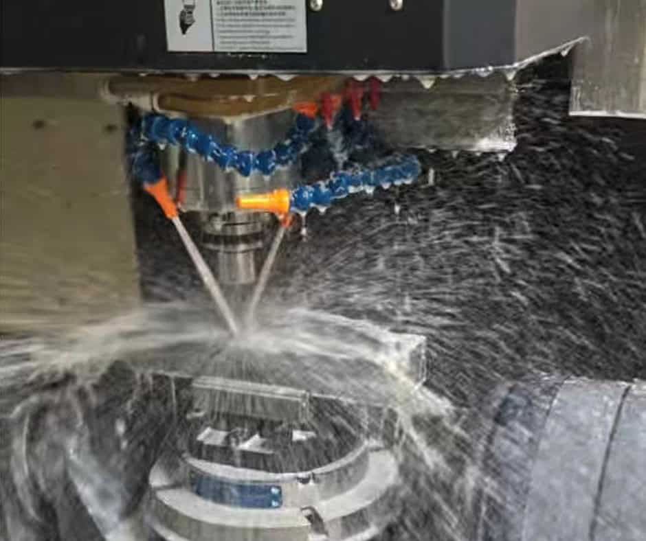
A Fiber Optic Adjustable Mirror Tube is well suited to precision CNC manufacturing because its geometry often combines cylindrical features, threaded interfaces, mounting holes, and planar reference surfaces.
CNC Turning
CNC turning can be used to produce the primary cylindrical body, external diameters, internal bores, shoulders, grooves, and coaxial features.
For tubular components, maintaining the relationship between internal and external diameters is often more important than simply achieving the nominal size of either feature independently.
CNC Milling
Milling is useful for mounting flats, slots, screw holes, flange features, locating surfaces, and other non-cylindrical geometry.
If the component includes several mounting features around a cylindrical body, CNC milling allows their positions to be controlled relative to established datums.
Drilling, Tapping and Reaming
Adjustment screws and mounting hardware commonly require tapped holes. Precision locating holes may require drilling followed by reaming when the functional fit calls for it.
Thread quality matters because adjustment mechanisms may be repeatedly assembled or adjusted.
Multi-Axis Machining
Multi-axis machining can be advantageous when mounting holes or surfaces are positioned around a cylindrical body or when several features must be machined from different orientations.
The need for multi-axis machining depends entirely on the geometry and drawing requirements.
Deburring and Cleaning
Deburring is particularly important for optical-mechanical components. Small burrs around holes, threads, or internal edges can interfere with assembly or generate particles.
After machining, the component should be cleaned appropriately for its intended application. The required cleaning level depends on the customer’s equipment and assembly environment.
Key CNC Machining Challenges
1. Maintaining Coaxial Relationships
A major challenge is maintaining the relationship between the internal bore, external cylindrical surface, and optical reference features.
This can be addressed through appropriate workholding, machining sequences, datum selection, and inspection methods.
2. Controlling Thin-Wall Deformation
Some mirror tubes are designed with relatively thin walls to reduce weight. Thin sections can deform under cutting forces or clamping pressure.
Machining parameters and workholding must therefore be selected to minimize distortion. In some cases, the machining sequence may need to leave sufficient material for subsequent finishing operations.
3. Producing Consistent Threads
Adjustment and retaining threads must provide predictable engagement. Excessive variation, burrs, or poor surface condition can affect adjustment behavior.
The thread specification should be clearly defined on the customer’s drawing rather than assumed from the component’s general appearance.
4. Accurate Hole Positioning
Mounting and adjustment holes may have a direct relationship with the optical axis. Their positional accuracy can therefore be more important than their simple diameter tolerance.
A suitable machining datum structure and coordinate inspection process can help control these relationships.
5. Protecting Functional Surfaces
Mating surfaces, optical-element seats, and locating features may require protection during machining and finishing. Scratches or dents on these areas can affect assembly accuracy even when the overall dimensions remain acceptable.
Quality Control
Quality inspection should be based on the features that determine the component’s actual function.
Depending on the drawing, inspection may include:
Overall dimensions
Internal and external diameters
Thread dimensions
Hole diameter and position
Concentricity or coaxial relationships where specified
Flatness
Parallelism
Perpendicularity
Surface finish
Functional fit
Visual condition and burr inspection
A CMM may be appropriate when multiple features must be verified relative to common datums. Calipers, micrometers, bore gauges, thread gauges, height gauges, optical measurement equipment, or other instruments may be used depending on the tolerance and geometry.
The important point is that inspection should reflect the customer’s engineering requirements. There is no reason to impose extremely tight tolerances on non-critical dimensions if they do not contribute to the component’s function.
Applications
Fiber-Optic Alignment Equipment
The tube can be used to position optical elements within fiber-optic alignment assemblies. Precision interfaces help maintain the intended relationship between the fiber path and optical components.
Laser Systems
Laser equipment often requires stable positioning of mirrors and related optical elements. An adjustable housing can simplify initial beam alignment and system setup.
Optical Measurement Instruments
In optical measurement equipment, mechanical alignment can influence measurement repeatability. Custom mirror tubes may therefore be designed around the instrument’s optical path and mounting architecture.
Photonics Research Equipment
Research systems frequently use customized optical configurations. Adjustable mechanical components allow engineers to modify optical arrangements without redesigning the entire housing.
Machine Vision and Imaging Equipment
Optical assemblies used for imaging may require controlled positioning of mirrors, lenses, or related elements. A custom-machined tube can integrate directly with the surrounding mechanical structure.
Optical Communication Equipment
Compact optical communication assemblies may require precise mechanical positioning while also imposing restrictions on size, weight, and thermal behavior.
Fiber Optic Adjustable Mirror Tube vs. Fixed Optical Tube
A useful comparison is between an adjustable mirror tube and a conventional fixed optical tube.
| Factor | Adjustable Mirror Tube | Fixed Optical Tube |
| Application | Systems requiring alignment or adjustment | Systems with predetermined alignment |
| Positioning | Adjustable during setup | Fixed after machining/assembly |
| Design complexity | Higher | Lower |
| Manufacturing | More interfaces and adjustment features | Generally simpler |
| Alignment flexibility | High | Limited |
| Cost | Usually higher for equivalent size | Usually lower |
| Best suited for | Prototyping, alignment-sensitive equipment, configurable systems | Stable production assemblies with established alignment |
A buyer should generally choose a Fiber Optic Adjustable Mirror Tube when the optical assembly requires mechanical adjustment, alignment flexibility, or serviceability.
A fixed optical tube may be the better choice when the optical position is already established and the priority is a simpler, lower-cost mechanical structure.
Cost and Procurement Considerations
The price of a custom Fiber Optic Adjustable Mirror Tube is determined by more than its raw material weight.
Material
Aluminum may reduce machining time and overall weight, while stainless steel can increase machining difficulty and material cost. The correct choice should be based on the application’s mechanical and environmental requirements.
Geometric Complexity
Multiple bores, threads, slots, angled features, and mounting interfaces increase programming, setup, tooling, and machining time.
Tolerances
Tight tolerances can require additional finishing operations, specialized tooling, more frequent inspection, and potentially slower machining.
Quantity
Prototype and low-volume production generally have higher unit costs because programming and setup costs are distributed across fewer parts.
As production volume increases, process optimization and fixture development can reduce the unit cost.
Surface Treatment
Anodizing, plating, passivation, polishing, painting, or other treatments add processing costs and may also require masking of specific functional surfaces.
Inspection
Basic dimensional inspection is different from comprehensive inspection involving CMM measurement, detailed inspection reports, or customer-specific quality documentation.
Typical Production Stages
Prototype: Suitable for validating mechanical interfaces and optical alignment.
Low-volume production: Appropriate for pilot equipment, specialized instruments, or early commercial production.
OEM production: Requires consistent process control and repeatable manufacturing.
Production quantities: May justify dedicated fixtures, optimized machining sequences, and process improvements to reduce unit cost.
Customization and Quotation
A Fiber Optic Adjustable Mirror Tube can be customized around the customer’s optical and mechanical interfaces.
Common customization options include:
Overall tube dimensions
Internal and external diameters
Wall thickness
Mounting-hole patterns
Thread specifications
Adjustment mechanisms
Optical-element seating features
Retaining features
Mounting flanges
Material
Surface finish
Surface treatment
Marking requirements
For an accurate quotation, buyers should ideally provide:
1.2D engineering drawing
2.3D CAD file, such as STEP or another compatible format
3.Material specification
4.Required quantity
5.Critical tolerances
6.Surface-finish requirements
7.Surface-treatment requirements
8.Inspection or documentation requirements
The 2D drawing is particularly important because a 3D model may define geometry without fully communicating tolerances, threads, surface finishes, datums, or inspection requirements.
For highly customized components, it is also useful to identify which dimensions are functionally critical. This helps the manufacturer focus machining and inspection resources where they have the greatest effect on performance.
FAQs
1. What is a Fiber Optic Adjustable Mirror Tube used for?
A Fiber Optic Adjustable Mirror Tube is used to mechanically support and position optical components while providing a means of adjusting their position or alignment. It can be used in fiber-optic, laser, photonics, imaging, and optical measurement equipment, depending on the design.
2. What material is best for a Fiber Optic Adjustable Mirror Tube?
There is no single best material. Aluminum is attractive for lightweight designs and efficient CNC machining, while stainless steel can be preferable when higher stiffness, durability, or corrosion resistance is required. The final choice depends on the design and operating environment.
3. Can a Fiber Optic Adjustable Mirror Tube be custom machined?
Yes. Custom CNC machining is often appropriate when the tube must match a proprietary optical assembly, mounting interface, thread configuration, or dimensional envelope. Custom features should be defined according to the customer’s engineering drawing.
4. What CNC processes are commonly used?
CNC turning is commonly used for cylindrical bodies, bores, shoulders, and coaxial features. CNC milling can produce mounting surfaces, holes, slots, and other non-cylindrical features. Drilling, tapping, reaming, deburring, cleaning, and surface treatment may also be required depending on the design.
5. How precise does the component need to be?
The required precision depends on the optical system. Not every dimension needs the same tolerance. Critical dimensions such as optical interfaces, mounting references, hole positions, and alignment-related features may require tighter control, while non-functional dimensions can often use more conventional tolerances.
6. What information should I provide when requesting a quotation?
A 2D drawing and 3D CAD model are the most useful starting points. Buyers should also specify material, quantity, critical tolerances, surface finish, surface treatment, and inspection requirements. If the component is part of an optical assembly, identifying the critical interfaces can further improve quotation accuracy.
Conclusion
A Fiber Optic Adjustable Mirror Tube is a relatively compact mechanical component, but its engineering requirements can be closely connected to the performance of the larger optical system.
The key challenge is not simply producing a cylindrical part. The manufacturer must control the relationships between bores, threads, mounting features, reference surfaces, and adjustment mechanisms while selecting materials and machining processes appropriate to the application’s requirements.
For lightweight equipment, aluminum may offer an effective combination of machinability and weight. For applications demanding greater stiffness or durability, stainless steel or another suitable material may be more appropriate. Similarly, an adjustable configuration provides valuable alignment flexibility, but it introduces additional manufacturing and inspection requirements compared with a fixed tube.
From a procurement perspective, the most reliable approach is to manufacture the component from a complete engineering drawing and CAD model, with critical tolerances and functional requirements clearly identified. This allows the manufacturer to select suitable CNC turning, milling, drilling, tapping, finishing, and inspection processes rather than applying unnecessary precision everywhere.
Ultimately, the right Fiber Optic Adjustable Mirror Tube is the result of balancing optical alignment requirements, mechanical stability, material behavior, manufacturability, inspection requirements, and production cost. For prototype, low-volume, OEM, or production applications, defining these requirements clearly at the quotation stage can significantly improve both manufacturing efficiency and final assembly performance.