Introduction: What Is a Beam Expander Mounting Plate?
Unlike general-purpose mounting plates, a beam expander mounting plate is engineered with strict dimensional tolerances to minimize misalignment, vibration, and deformation that could negatively affect beam quality or optical accuracy.
Its primary functions include:
Supporting and fixing beam expanders securely
Maintaining accurate optical axis alignment
Providing repeatable positioning during installation or maintenance
Improving structural rigidity within optical assemblies
Reducing vibration-induced optical errors
These mounting plates are commonly manufactured from 6061-T6 aluminum, 7075 aluminum, or stainless steel (304/316) depending on the application requirements.
Typical material advantages include:
Aluminum alloys: Lightweight, corrosion-resistant, excellent machinability, and suitable for anodizing.
Stainless steel: Higher rigidity, superior wear resistance, and excellent corrosion resistance in demanding environments.
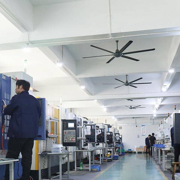
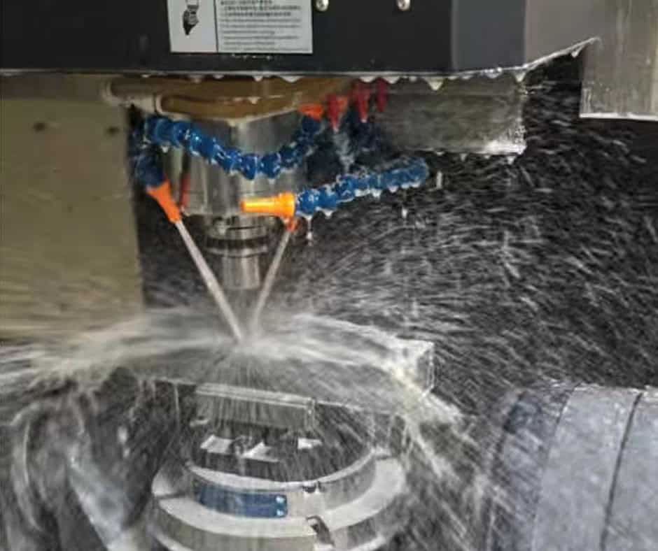
Most beam expander mounting plates are produced using high-precision CNC milling, allowing manufacturers to achieve excellent flatness, accurate hole positioning, smooth surface finishes, and repeatable production quality.
Table of Contents
Terminology & Standards (Common Names & Industry Terminology)
Depending on the manufacturer or industry, this component may be referred to by different names, including:
Beam Expander Mounting Plate
Beam Expander Base Plate
Optical Mounting Plate
Laser Beam Expander Bracket
Beam Expander Adapter Plate
Optical Fixture Plate
Laser Mount Plate
Optical Equipment Mount
Although these names are often used interchangeably, slight design differences may exist.
For example:
Mounting Plate generally refers to a flat precision base.
Adapter Plate connects components with different mounting patterns.
Bracket usually includes vertical or angular support features.
Fixture Plate often incorporates locating pins or precision reference surfaces.
Manufacturing Standards
Unlike standardized fasteners, beam expander mounting plates are typically manufactured according to customer drawings and assembly requirements rather than a universal dimensional standard.
However, manufacturing commonly follows international quality standards such as:
ISO 2768 — General dimensional tolerances
ISO 1101 — Geometric Dimensioning and Tolerancing (GD&T)
ISO 286 — Fits and tolerances
ISO 9001 — Quality management systems
ASTM B221 — Aluminum alloy material specifications
ASTM A240 — Stainless steel plate specifications
In most OEM projects, the customer’s engineering drawing remains the primary manufacturing reference.
Performance Characteristics (Key Features)
1. High Structural Rigidity
The mounting plate provides a rigid mechanical foundation that prevents unwanted movement or deformation during equipment operation.
This rigidity is particularly important in precision laser systems where even microscopic displacement can affect beam alignment.
2. Excellent Dimensional Accuracy
CNC machining enables extremely accurate machining of:
Mounting holes
Threaded holes
Precision pockets
Datum surfaces
Accurate positioning minimizes assembly errors and improves optical repeatability.
3. Superior Flatness
The contact surface must remain exceptionally flat to prevent stress-induced distortion of optical components.
Controlled machining and inspection ensure consistent flatness across the mounting surface.
4. Corrosion Resistance
Depending on material selection and surface treatment, the mounting plate offers long-term resistance against:
Humidity
Industrial environments
Cleaning chemicals
Laboratory conditions
Common finishes include:
Clear anodizing
Black anodizing
Hard anodizing
Passivation
Electropolishing
5. Stable Clamping Performance
Properly designed mounting holes and locating features distribute clamping forces evenly, preventing localized deformation.
Stable fastening helps maintain precise optical alignment over extended operating periods.
6. Excellent Surface Quality
Precision CNC machining followed by deburring and surface finishing produces smooth edges and clean surfaces.
High-quality finishes reduce contamination risks and improve assembly efficiency.
7. Long-Term Reliability
Quality materials combined with controlled manufacturing processes provide excellent durability under repeated installation, vibration, and thermal cycling.
Comparison: Beam Expander Mounting Plate vs. Optical Mounting Bracket
| Comparison Item | Beam Expander Mounting Plate | Optical Mounting Bracket |
| Primary Application | Mounting beam expanders on optical systems | Supporting mirrors, lenses, sensors, or optical instruments |
| Performance Focus | High positioning accuracy and flatness | Structural support with adjustable positioning |
| Manufacturing Process | Precision CNC milling with tight tolerances | CNC machining, welding, or assembled structures |
| Cost | Moderate to high depending on precision | Wide cost range depending on complexity |
Which One Should You Choose?
Choose a Beam Expander Mounting Plate when:
Optical axis alignment is critical.
Beam expander positioning requires high repeatability.
Flatness and hole accuracy directly affect system performance.
Choose an Optical Mounting Bracket when:
Multiple optical components require adjustable positioning.
Structural support is more important than ultra-high positioning precision.
Angular or vertical mounting is required.
Manufacturing Considerations (CNC Machining & Production)
Typical Manufacturing Process
A typical production workflow includes:
1.Raw material preparation
2.CNC milling
3.Precision drilling
4.Counterboring or countersinking
5.Thread tapping
6.Precision pocket machining
7.Edge chamfering
8.Deburring
9.Surface finishing
10.Cleaning
11.Dimensional inspection
12.Packaging
Material Selection
6061-T6 Aluminum
Advantages:
Lightweight
Excellent machinability
Good corrosion resistance
Cost-effective
Easy anodizing
Suitable for most laser equipment.
7075 Aluminum
Advantages:
Higher mechanical strength
Better rigidity
Reduced deformation
Suitable for high-performance optical equipment.
Stainless Steel 304
Advantages:
Excellent corrosion resistance
Good toughness
Attractive appearance
Often used in laboratory environments.
Stainless Steel 316
Advantages:
Superior chemical resistance
Better marine corrosion resistance
Longer service life in harsh environments
Suitable for demanding industrial applications.
Manufacturing Challenges
Producing a high-quality beam expander mounting plate involves overcoming several technical challenges:
Maintaining precise hole position tolerances
Controlling overall flatness
Achieving perpendicularity between machined features
Preventing distortion during machining
Managing thermal expansion during precision cutting
Maintaining thread quality
Preventing burr formation around small holes
Advanced CNC machining centers and precision inspection equipment are typically required.
Post-Processing
After machining, manufacturers generally perform:
Deburring
Ultrasonic cleaning
Surface treatment
Thread inspection
Coordinate Measuring Machine (CMM) inspection
Visual inspection
Protective packaging
Applications (Where Is It Used?)
Laser Equipment
Supports and aligns beam expanders used in laser cutting, laser marking, and laser welding systems.
Optical Instrumentation
Provides stable mounting for optical assemblies requiring precise beam alignment in scientific and industrial instruments.
Industrial Automation
Integrates optical components into automated inspection systems and machine vision equipment.
Medical Laser Devices
Ensures stable positioning of beam expanders used in surgical and diagnostic laser equipment.
Semiconductor Manufacturing
Supports precision optical systems used in lithography, wafer inspection, and laser processing equipment.
Research Laboratories
Used in experimental optical benches where repeatable positioning and alignment are essential.
Cost Factors (What Influences Price?)
Several factors influence the manufacturing cost and purchasing decision for a beam expander mounting plate.
Material Grade
Higher-grade materials such as 7075 aluminum or 316 stainless steel generally increase material costs compared to standard 6061 aluminum or 304 stainless steel.
Machining Complexity
Costs rise with:
Multiple machining operations
Deep pockets
Precision threaded holes
Tight positional tolerances
Complex geometries
Tolerance Requirements
High-precision optical applications often require stricter tolerances, increasing machining time and inspection requirements.
Surface Treatment
Common finishing options include:
Black anodizing
Clear anodizing
Hard anodizing
Passivation
Electropolishing
Each process affects both appearance and cost.
Inspection and Certification
Additional quality requirements such as:
CMM reports
Material certificates
First Article Inspection (FAI)
Full dimensional reports
may increase production costs.
Order Quantity
Production volume significantly affects unit pricing:
Prototype machining
One-off custom parts
Low-volume production
Medium-volume manufacturing
OEM mass production
Higher quantities generally reduce per-piece costs.
Common Supply Options
Manufacturers typically provide:
Fully finished components
Rapid prototypes
Low-volume production
OEM custom manufacturing
Complete assembly support
FAQs (Frequently Asked Questions)
1. What is the primary purpose of a Beam Expander Mounting Plate?
Its primary function is to securely mount and accurately position a beam expander while maintaining precise optical alignment within a laser or optical system.
2. Why is aluminum commonly used for these mounting plates?
Aluminum alloys such as 6061-T6 offer an excellent balance of lightweight construction, strength, corrosion resistance, machinability, and cost-effectiveness. They also accept anodized finishes that improve durability and reduce reflections.
3. Can Beam Expander Mounting Plates be customized?
Yes. Most are custom-manufactured based on customer drawings, including dimensions, mounting patterns, threaded holes, locating features, material selection, and surface finishes.
4. What manufacturing process is typically used?
High-precision CNC milling is the primary process, combined with drilling, tapping, pocket machining, deburring, surface finishing, and comprehensive quality inspection to ensure dimensional accuracy and reliable assembly.
5. What information is required for an accurate quotation?
To provide an accurate quotation, manufacturers typically require:
2D drawings or 3D CAD files (STEP, IGES, DWG, etc.)
Material specification
Surface finish requirements
Dimensional tolerances
Quantity
Inspection or certification requirements
Delivery schedule
6. How is quality verified before shipment?
Quality is typically verified through dimensional inspections using CMMs and precision gauges, visual checks, thread verification, flatness measurements, and review of material certifications when required.